Paul,
measurement is in this project. Measured from ~1m, mic placed between WG and midrange. It also shows cabinet it was measured in.
N164 :: Pkaudio
Attached image shows the idea of mounting. I am sorry, this was one of my first projects, I do not have detailed photos. Orange color represents 3mm mdf ring, sitting on the WG, I used silicon glue to fix it, it also added some weight and supressed resonances. After that I used another 3mm ring, representing by red line, and sanded away the rest of the throat. After sanding, that "red" ring is removed, and you can fit the tweeter, just press it with 4 bolts and another piece of MDF . These 3+3mm provided the right throat diameter. You will have to experiment a bit. Photo with blue plastic shows just the first version of attachment, used for testing, but it shows the idea.
Your photo/drawing illustrates the approach nicely. When removing part of the throat (the stuff above the red line in your photo/drawing), you increased the throat diameter. I don't know about the XT25, but the Scan 6600 needs this slightly larger diameter to make the WG300 fit.
I made a bunch of aluminium adapter rings using Front Panel Express (see here), and I have some spares. If anyone wants a set or the Front Panel file, let me know. They will fit the 6600, and some other Scans (but not all -- don't ask me which ones).
Pida, did you see the "bass reflex" issue with the XT25 as I observed with the 6600?
I saw it only in my SS6600/WG148R measurement. It was testing measurement so I did not try to fix it.
I measured XT25/WG300, SS7100/WG148, SS7000/WG148, none of them showed that "bassreflex" issues.
I will make a built with SS7000/WG148R soon so I will definitely plug the bolt holes with the bolts and glue, just to be sure.
I measured XT25/WG300, SS7100/WG148, SS7000/WG148, none of them showed that "bassreflex" issues.
I will make a built with SS7000/WG148R soon so I will definitely plug the bolt holes with the bolts and glue, just to be sure.
Pida, did you see the "bass reflex" issue with the XT25 as I observed with the 6600?
Last edited:
The amplifier power will not be dissipated at 90% because crossover splits signal in different paths, so only 90% of the power at HF path will be dissipated.
Of course 🙂.
I didn't want to say to skip the CD driver. If you really like a CD in your system, you have to apply it...
At this time I hop from one tweeter concept to the other to find the best solution.
I was wondering, what about the AMT with horn.
If you look for example to the Dayton Audio PHT1-6 and see the mechanical drawing, the acoustical center is close to what we need.
Dayton Audio PHT1-6 Planar Horn Tweeter 6 Ohm
Also the Mundorf AMT with horn seem to have similar AC, but I don’t find the mechanical drawing of them at this moment. Of course these are not cheap.
Beyma TPL 150H AC is 80 mm deep.
In case of interest in such kind of drivers, I have to check DI also.
Paul that Dayton PHT1-6 has rather high suggested XO is that ok ?
also Mundorf AMT19CM2.1-C.
I did bring up the padding issue for CDs but it was ignored so I thought it is ok, at this point, we do not have a waveguide or horn for right AC alignment. we may need to move on, I did a lot of search and couldn't find a suitable solution, even the suggested TPL150H is 80mm deep as Paul mentioned before, we either have to go with a custom made WG which can take a long time and TBH I wouldn't go with it at this point or make peace with with a none aligned design.
Last edited:
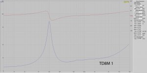
the first measurements after 12 hours burning for each driver. they are still under load for at least another 12 hrs.
the td8m vas cal is with added mass method, I do not trust it much since i used a big tape as weight.
this is just for demonstration, numbers are vary on each try, I ll have more accurate numbers hopefully tomorrow.
the td8m vas cal is with added mass method, I do not trust it much since i used a big tape as weight.
this is just for demonstration, numbers are vary on each try, I ll have more accurate numbers hopefully tomorrow.
Attachments
Last edited:
that Dayton PHT1-6 has rather high suggested XO is that ok ?
also Mundorf AMT19CM2.1-C.
These two types have a high resonance frequency, that's the reason why the suggested XO is so high. Sorry, I didn't look in that detail now.
If 2.5kHz is a possible option with the Dayton, I did look to the DI.
I can only calculate the DI in a single horizontal plane +/-45 degrees, because I have no more measurements. But it gives an idea.
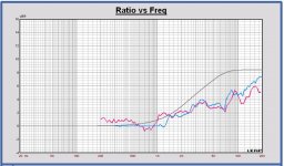
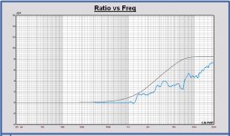
In the first plot, the DI of the AE TD8M in grey and the Dayton PHT1-6 in blue. A XO at 2500Hz is a possibility.
In the second plot I have added the DI of the Monacor TD300-WG300 in red to compare with, also a DI value in a +/-45 deg window. The DI response of the Dayton is almost the same as the WG300.
Remark again that these are DI values in a +/-45 deg horizontal plane. In a single hemisphere (that is incl. vertical response and +/-90 deg window) the DI of the Dayton will be higher than the Monacor waveguide, but I expect it can still be used together with the AE TD8M.
A minus point is the SPL fall off above 10 kHz. At 20 kHz the sensitivity is about 88 dB, but 90 dB up to about 18 kHz.
Looking to the mechanical drawing, the acoustical center of this driver is almost the same as the TD8M.
Attachments
Last edited:
the first measurements after 12 hours burning for each driver. they are still under load for at least another 12 hrs.
the td8m vas cal is with added mass method, I do not trust it much since i used a big tape as weight.
this is just for demonstration, numbers are vary on each try, I ll have more accurate numbers hopefully tomorrow.
So much ripple on the impedance curve? It looks the tape is vibrating or the measurement signal is too low.
...
I did bring up the padding issue for CDs but it was ignored so I thought it is ok, ...
It is not a problem at all, padding down is a solution to a problem, "padding up" on the other hand, is impossible.
And looking at the frequencies involved, power should not be an issue with regards to heat dissipation.
Last edited:
So much ripple on the impedance curve? It looks the tape is vibrating or the measurement signal is too low.
mm not sure what is going on, this is free air measurement no added weight at this point. I never got all smooth impedance curve but not like this, I usually measure a driver in cabinet tho, this is just the driver sitting on the table, any tips ?
Last edited:
It is not a problem at all, padding down is a solution to a problem, "padding up" on the other hand, is impossible.
And looking at the frequencies involved, power should not be an issue with regards to heat dissipation.
Hey Kaffimann 🙂 padding up ? 😀 that would be sweet, haha.
So much ripple on the impedance curve? It looks the tape is vibrating or the measurement signal is too low.
Good to know, my experience with Dayton Audio is limited, and I couldn't find much reviews on this driver, what do you guys think ? an 80$ AMT ? 🙂
mm not sure what is going on, this is free air measurement no added weight at this point. I never got all smooth impedance curve but not like this, I usually measure a driver in cabinet tho, this is just the driver sitting on the table, any tips ?
Maybe the table is vibrating, you could try to put a soft rubber between driver and table
Of course 🙂.
I didn't want to say to skip the CD driver. If you really like a CD in your system, you have to apply it...
Probably the extra efficiency will translate into lower distortion, can't wait for measurements comparison.
Crossing fingers and enjoying the project regardless the final solution.
Maybe the table is vibrating, you could try to put a soft rubber between driver and table
probably, I have some rubber mat somewhere, I ll try to have better isolation next time.
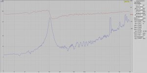
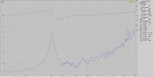
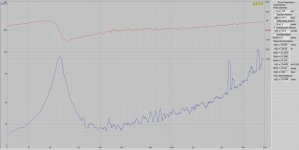
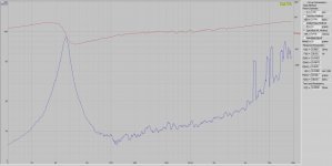
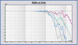
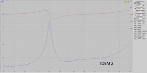
Got new measurements, it's after 22 hours of burning, what do you think ?
in the 3rd pic, the TD8M 1 is on the Left and TD8M 2 is on the right and in the middle is the factory measurements. I still wouldn't count on the VAS and the MMS numbers since I just added that by known SPL method, no "added weight".
in the 3rd pic, the TD8M 1 is on the Left and TD8M 2 is on the right and in the middle is the factory measurements. I still wouldn't count on the VAS and the MMS numbers since I just added that by known SPL method, no "added weight".
Attachments

Last edited:
Aatto,
Can you create some frd files of the impedance curves? Then I look in Leap also.
Just to know, did you measured a reference resistor, some 1% type for example?
The piston diameter calculated out of the specification is 155 mm, in your sheet it is 170 mm.
I checked the datasheet values of the TD8M in the past. If I use those TSP values, the SPL at 2.83Vrms is correct. So I think your piston diameter of 170 mm is too high. With a 155 mm value, you will get other TSP values.
The specified SPL method can give you a first indication of the parameters, but it isn't the good method, unless you do measure yourself the SPL value.
The SPL value is a result of the TSP parameters of 'your' driver.
Last edited:
Good to know, my experience with Dayton Audio is limited, and I couldn't find much reviews on this driver, what do you guys think ? an 80$ AMT ? 🙂
It is not an AMT, but a planar-magnetic tweeter, sometimes called a quasi-ribbon, a cheaper version of a ribbon.
It should be interesting to know some practical experiences of such tweeter at first, indeed.
Last edited:
So much ripple on the impedance curve? It looks the tape is vibrating or the measurement signal is too low.
mm not sure what is going on, this is free air measurement no added weight at this point. I never got all smooth impedance curve but not like this, I usually measure a driver in cabinet tho, this is just the driver sitting on the table, any tips ?
The excessive ripple of the first measurement might be due to too low (noise) or too high (clipping) levels of the measurement signals.
Don't measure the drivers sitting on a table or on the floor. They need to "breathe", and you must not block the rear ventilation of the magnet. You need to mount them in free air. My cheap and dirty approach is usually to clamp the drivers between my knees during the measurement. But I am sure there are cleaner ways of doing that 🙂
Got new measurements, it's after 22 hours of burning, what do you think ?
How did you do the burn in? Signal type, voltage levels?
Anyway, I don't like the humps occurring at 600 Hz and at higher frequencies. These features indicate some resonance effects in the driver (suspension or cone breakup). They are deep in the intended pass band.
It is not a problem at all, padding down is a solution to a problem, "padding up" on the other hand, is impossible.
You could use an autoformer. Autoformers pass the full power and allow adjusting drive voltage levels in both ways (up or down). But yes, this approach is not very common in loudpeakers
Don't measure the drivers sitting on a table or on the floor. They need to "breathe", and you must not block the rear ventilation of the magnet. You need to mount them in free air. My cheap and dirty approach is usually to clamp the drivers between my knees during the measurement. But I am sure there are cleaner ways of doing that 🙂
Or measuring the drivers on IEC baffle, if available. Parameter measurement is a little different. In Leap it is possible to make a 'free air' or 'infinite baffle' transducer model.
Pcgab:
How about your large IEC baffle? Are you gonna install one 🙂?
Last edited:
- Home
- Loudspeakers
- Multi-Way
- Open Source "Tower XL"