Whoa! Is there any documentation for this kind of stuff?
I already ordered the first set of prototype boards, but I don't expect them to be perfect. The custom rules may be useful for the next prototype 😎
I already ordered the first set of prototype boards, but I don't expect them to be perfect. The custom rules may be useful for the next prototype 😎
Pfft. A link that returns a 404. Sigh.
Try https://docs.kicad.org/8.0/en/pcbnew/pcbnew.html#custom-design-rules
[Edit: the link probably does work for regular builds. It just doesn't work in development builds.]
Try https://docs.kicad.org/8.0/en/pcbnew/pcbnew.html#custom-design-rules
[Edit: the link probably does work for regular builds. It just doesn't work in development builds.]

First prototype boards are in, most parts are in, so building begins!
- Heater supply for the input tubes is built and works.
- Time delay for B+ and B- is built and seems to work (may need more testing).
- High-voltage supply for negative bias and buffer stage is built and works.
- B+ and B- supply is built, but not yet tested.
Attachments
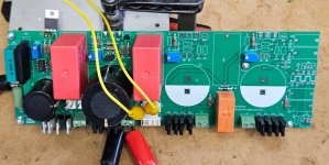
Finished building the PSU board. Received the Toroidy mains transformers and hooked them up. Works 🙂
I am not sure what's the best way to measure the high voltage of the stator bias. The internal resistance of the DVM pulls down the voltage immediately when I touch the HV pin. I might try charging a large capacitor to buffer the voltage and then take a reading off this.
I need to find a chassis to continue with a somewhat more self-contained prototype build. I don't feel comfortable with all that high voltage floating around the wire mess on my workbench...
A 10G HV resistor makes a nice 1000:1 attenuator with the 10M input resistance of most vanilla DVM.
Direct reading, 1KV = 1V.
This works well with the 6.5KV of the Quad ESL57.
The syringe is only for show.

I previously used a string of 10 or 22M resistors to make a 100:1 attenuator.
Direct reading, 1KV = 1V.
This works well with the 6.5KV of the Quad ESL57.
The syringe is only for show.
I previously used a string of 10 or 22M resistors to make a 100:1 attenuator.
AAAAAAAARGHHHH!!!!
The pin numbering of the tube sockets is backwards in KiCad. WTF!? I'll have to mount the tubes on the back side of the PCB... 💩
I'll have to redo the amplifier PCB.
The pin numbering of the tube sockets is backwards in KiCad. WTF!? I'll have to mount the tubes on the back side of the PCB... 💩
I'll have to redo the amplifier PCB.
Lots of prototyping and testing done during the past few days:
- Tested the BIAS supply voltage using the 10G resistor borrowed by @Zung. Voltage is 575 VDC, which is less than 1% off the 580 V target.
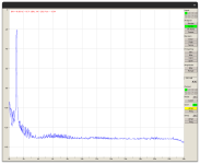
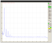
- Built and tested the input stage (with the tubes on the back of the PCB 🙄). Works well. Output from the IPS goes up to 300 Vpp, where it starts clipping. Transients show no ringing. Output is flat up to 720 kHz (-6 dB). I attached screenshots of the harmonic spectra at 1 Vrms and 10 Vrms output.
- Built and tested the Coleman DHT Filament regulators. They work as expected running off a bench PSU. Still need to make the raw DC supplies for the Coleman boards.
- The buffer stage does not yet work. I messed up the circuit and the pinout of the FETs in the buffer stage right before sending out the gerbers for PCB manufacturing. It took me a while to figure out these problems. I also had a few hickups due to probe slips and brain malfunction, killing the pass devices on the HV supplies a few times, and even a 6E5P tube 😡.
Attachments
New amplifier boards, new progress. Input and buffer stage now works fine.
Worked on DHT filament supplies. Raw DC supply and Coleman regulators work fine.
Built output stage. Gyrator made some noise and then smoke. Turns out I screwed up the FET pinouts again on the PCB. Jeez!!! How low can I go?
I'll try hacking the board and hopefully I can make some more progress with new FETs in the Gyrator.
"How low can I go ?"
Never ask that IMO, it can be a looooooooong ways....
Persevere, you will get it
Never ask that IMO, it can be a looooooooong ways....
Persevere, you will get it
Ok, I could go lower... I killed the B+ HV supply this afternoon. 😡"How low can I go ?"
Time for a break.
She's alive!
No music yet (need to rebuild the bias supply on the new boards first), but the scope shows pretty test signals.
It was as rough ride until I got here. Sorry to all those transistors that had to die in the process. Some of them said goodbye with a loud bang and some smoke, others went silently. I guess there will be more following this path, and there will be more iterations of improved PCB designs... but I'll stop here for today!
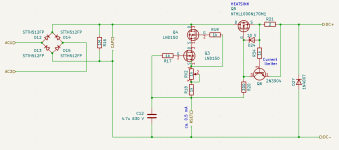
Before I proceed with in-depth testing of the audio performance, I need to better understand a few things that keep going wrong from time to time. One of these things is the current limiter of the high-voltage power supply (schematic attached).
Resistor R21 and BJT Q6 are meant to act as a current limiter that protects the power supply in case of overload or a short at PSU output (yes, that happens...). If there's enough output current to drop 0.65 V across R21, Q1 will turn on, pulling the gate of Q5 low until the current is below the threshold for the 0.65 V drop across R21. This is the conventional wisdom for this type of current limiter.
However, there's a problem with the current limiter in this cap multiplier circuit. If the output is shorted, the BJT Emitter sees 0 V, while the Collector sees the voltage of capacitor C12, which is charged to 440 V or so. The C-E voltage of 440 V will kill most BJTs. Even if the BJT would survive this high voltage, C12 would be shorted via the BJT, causing a rather high current through the BJT, destroying the BJT. In other words, the current limiter dies when it's trying to do its job.
I tried inserting a resistor between the BJT Collector and the gate of Q5. The idea was that this resistor would drop some of the C12 voltage and limit the current flow through the BJT. However, the resistor value needed to keep the voltage and current limits of Q5 was rather large, stopping the current limiter from doing its job.
Any thoughts how this could be solved, or for a different type of current limiter that does not suffer from this issue?
Attachments
Do you still have the issue when you increase R20? The transistor now has to conduct almost 1.5 A, which it may not be able to.
A ZTX458 could handle 400 V, but not 440 V. Maybe you could cascode the NPN with a high-voltage depletion MOSFET. When there is no voltage headroom for it, it will work as a switched-on switch.
A ZTX458 could handle 400 V, but not 440 V. Maybe you could cascode the NPN with a high-voltage depletion MOSFET. When there is no voltage headroom for it, it will work as a switched-on switch.
I was thinking of increasing R20, but felt like it's a bad idea. Increasing R20 would degrade the high-frequency performance of the cap multiplier by lowering the RC pole formed by R20 and the gate capacitance of Q5 (about 200 pF or slightly less).
However, running the numbers I think it might not be too bad. For example R20 = 1.5 kOhm --> R x C = 1500 x 200e-12 = 0.3 microseconds corresponding to 1/2pi/0.3us = 53 kHz. Performance would not be affected in the audio band.
Also, with 440 V across an 1.5 kOhm resistor, the current through the BJT would be limited to 0.3 A. A ZTX458 might be okay, or otherwise a ZTX658 would be worth a try.
Next question!
There's a bit of oscillation on the output. The scope shows the oscillation at about 2 MHz.
The voltages in the driver and buffer stages don't show any oscillation. The active loads of the DHT tubes are also clean. The oscillation only shows up at the output tubes (VT-25 DHTs in my test build). If the output tubes are replaced with dummy resistors, there is no oscillation anywhere in the entire circuit. I guess that means the oscillation happens by HF noise pickup in/at the output tubes.
That's not surprising, because the tubes are connected to the PCB with a about 20 cm long leads. While the final builds may use shorter leads, there will always be some length of wire that may pick up HF noise.
The grid stoppers are soldered directly to the pins of the tube sockets. I could improve the oscillation a bit by increasing the grid stopper resistors from 100 Ω to 220 Ω. I could probably increase them further to improve things more. However, since the DHT grids may swing positive and draw a bit of current, and larger grid stopper resistors would interfere more with the grid voltage.
What other options are there? RC snubbers? Ferrite beads? How, where? Something else?
- Home
- Amplifiers
- Headphone Systems
- Open Source DHT Estat Headphone Amp -- OSDEHA