Oups. I fell into the rabbit hole of electrostatic headphones. Those estats sound really nice to my ears!
Estats work at high voltage and low currents, so they can (and should!) work directly off the anode(s) of some nice vacuum tube(s). No transformers getting in the way!
There are a few estat tube amps out there. However, I could not find one that fits my needs (or wishes). The amp should be somewhat compact, and I want an output stage using directly heated triodes (DHTs). So I started thinking about designing a new amp. Maybe we can pull this off similarly to the OSMC project, which was great because severeal DIYers contributed to the design. Everyone is encouraged to contribute to the design process here!
Here is a (preliminary) list of some design goals (that may be updated in the future):
Warning: This DIY project involves high voltage. Individuals utilizing the information provided must possess expert knowledge, adhere to stringent safety precautions, and accept all risks associated with electrical work. The authors and contributors of this project expressly disclaim any liability for injuries or damages arising from the use or misuse of this information.
Estats work at high voltage and low currents, so they can (and should!) work directly off the anode(s) of some nice vacuum tube(s). No transformers getting in the way!
There are a few estat tube amps out there. However, I could not find one that fits my needs (or wishes). The amp should be somewhat compact, and I want an output stage using directly heated triodes (DHTs). So I started thinking about designing a new amp. Maybe we can pull this off similarly to the OSMC project, which was great because severeal DIYers contributed to the design. Everyone is encouraged to contribute to the design process here!
Here is a (preliminary) list of some design goals (that may be updated in the future):
- Use DHT tubes for output stage.
- Output is taken directly from the anodes of the DHT output tubes. No transformer or capacitors to transfer the power to the headphones.
- Input must take balanced input at signal levels of modern audio sources (mostly DACs these days).
- Input stage and other circuit elements are welcome to use solid-state parts where suitable. I don't intend this to become a nostalgia festival.
- Focus is on quality of audio reproduction and electronic design, not on low cost.
- The finished amp should be reasonably compact.
- The design is intended for use in the DIY community. If this project goes anywhere, full documentation will be provided in a public repository. Any use of the design (including commercial) will be allowed, but any modifications or extensions to the design that are used beyond one-off DIY builds for personal use are required to be re-published (and preferrably be fed back to this project).
- Auridux amplifier by @dddac
- Some great information on DHTs and tube design concepts by @mogliaa
- Blue Hawaii estat amp by @kevin gilmore
- Megatron amp by @kevin gilmore
- Some (long) threads on the DIY T2 (1 and 2) and Mini T2 amplifiers
- The only DHT estat amp I found, I believe by @hpeter
- A few estat amps with/without tubes at High-Amp (Andreas Rauenbühler)
- Schematic of the Stax SRM-007T amplifier (most of the other Stax tube amps use the same circuit)
- DHT headphone amp stuff, although not for estats
- Tube CAD article on estat tube amps, and another one, and yet another one
Warning: This DIY project involves high voltage. Individuals utilizing the information provided must possess expert knowledge, adhere to stringent safety precautions, and accept all risks associated with electrical work. The authors and contributors of this project expressly disclaim any liability for injuries or damages arising from the use or misuse of this information.
Last edited:
To start off, let's look at the output stage:

The following are some thoughs on how much clean signal swing (voltage and current) we need from the output. What does everyone think about these numbers?
TLDR: I'd suggest a minimum of 500 V and 20 mA (peak values) before the amp goes into clipping.
Voltage swing:
- No transformers, no capacitors, so it cannot be single ended. Push-pull it is!
- The output stage needs to drive very high impedance estat headphones. To make sure the audio/AC power is used efficiently into the headphones, the anode loads need to present a (much) higher AC impedance to the anodes. So we're looking at constant-current loads (current sources/sinks, CCS). CCS loads also help with optimizing the linearity and voltage gain of the amplifier, and with suppressing ripple and noise from the +HV rails.
- The gyrator CCS type (as discussed by @mogliaa and others) works as a CCS in the audio/AC domain, but provides a fixed voltage at DC. This may be a useful feature to fix the DC voltages at the anodes, and hence to adjust and maintain the amplifier outputs close to 0 V.
The following are some thoughs on how much clean signal swing (voltage and current) we need from the output. What does everyone think about these numbers?
TLDR: I'd suggest a minimum of 500 V and 20 mA (peak values) before the amp goes into clipping.
Voltage swing:
- The goal for the dynamic peak (!) SPL levels from headphones is often considered at about 110 dB-SPL. With a typical estat sensitivity of approx. 100 dB-SPL @ 100 Vrms, the output would need to swing 316 Vrms = 450 Vpk = 900 Vpp without clipping.
- Most Stax amps are specified to 300...470 Vrms output. The Stax T2 is specified to 630 Vrms. The Blue Hawaii is specified to 570 Vrms.
- I am not a fan of playing headphones extremely loud, but I do think that there should be ample headroom to reproduce peak signals without compression/clipping. Let's aim for a clean output swing of at least 500 Vpk (1000 Vpp).
- If the estat is modelled as simple capacitor with a typical capacitance of C = 100 pF (that's surely not be the most accurate model of an estat!), the current I is determined by the rate of change of the voltage U at the output:
I = C x dU/dt
The minimum required slew-rate (dU/dt) seems to be a matter of debate. The internet is full of numbers, but some data presented by respected designers were in the range of 0.04...1.2 V/µs (normalized to an output of 1 Vpk). For a 500 Vpk output, this translates to dU/dt = 20...600 V/µs, or I = 2...60 mA. That's quite a wide range, and my gut feeling is that 60 mA may be a bit much. - Driving the capacitance with a sine signal at 500 Vpk, the peak current would be 6.2 mA at 20 kHz, 16 mA at 50 kHz, or 31 mA at 100 kHz. We may not need to drive the estats to full output at 100 kHz, and the power spectrum of music signals is typically quite a bit lower at treble frequencies.
- Given the above numbers, let's aim for a clean output swing of at least 20 mA-peak.
How well does this super simple model work out? I made a few measurements using my Stax X9000 headphone. This figure shows that the model is surprisingly accurate:If the estat is modelled as simple capacitor with a typical capacitance of C = 100 pF (that's surely not be the most accurate model of an estat!), the current ... Driving the capacitance with a sine signal at 500 Vpk, the peak current would be 6.2 mA at 20 kHz, 16 mA at 50 kHz, or 31 mA at 100 kHz. We may not need to drive the estats to full output at 100 kHz, and the power spectrum of music signals is typically quite a bit lower at treble frequencies.
Here are some considerations on voltages/currents @ ?kHz on the load (100pF).
http://www7b.biglobe.ne.jp/~konton/STAX Drive Amp.htm
Google doed a good translation.
http://www7b.biglobe.ne.jp/~konton/STAX Drive Amp.htm
Google doed a good translation.
Good stuff, thanks! The article seems to follow the same logic as my guesstimates in the previous posts, and then also confirms this using some SPICE simulations. The article also points out that typical music has relatively low high-frequency power, so there is some room for compromise on the max. current needed from the output stage.
A low power headphone amplifier?
That looks like a nice circuit topology; all you have to do is design it properly to get good performance.
There are lots of knowledgeable readers and posters in Tubes / Valves who can help.
Or,
Output transformers can be your friend.
Capacitors can be your friend.
You do not want capacitors to be in series with the signal path?
B+ capacitors are in series with your signal path (even with a CCS, the CCS has to do its job of reducing any capacitor 'grunge' [if grunge does exist]).
Or just use Batteries for your B+
The recording studio uses capacitors. Power supplies, coupling caps, condenser microphones, etc.
The capacitance of the Electrostatic headphones does not seem to be a problem; why are other capacitors suddenly a problem?
Does the physics for electrostatic headphones not apply to amplifier capacitors?
"Make things as simple as possible, but no simpler" - Albert Einstein
Starting with simple, there is nothing that can not be made more complex than it has to be.
Have Fun!
Last edited:
@6A3sUMMER By "no transformer or capacitor" I was referring specifically to the coupling of the power output to the headphones. It is not my intention to completely ban those parts in the entire circuit.
My experience is that DC blocking caps of reasonable quality don't do anything that can be heard, as long as they don't pass any substantial current (very different story with loudspeaker xover caps that do pass current!).
Cyrill Bateman did some very interesting work on the (non-)distortion caused by capacitors: https://linearaudio.net/cyril-batemans-capacitor-sound-articles
Just to really convince myself I did another test to determine the output voltage/current needed from the amp.
I used my RTX6001 audio analyser as the audio source, a Stax SRM700T amp, and the Stax X9000 and Hifiman Shangri La Jr headphones. The Hifiman seems a bit less sensitive to my ears than the Stax, so I used to Hifiman for the numbers below.
(It seems my previous guesstimate of 1000 Vpp was a bit too low.)
While I was at it, I also measured the peak current. I inserted a 1000 Ohm current sensing resistor in the output and measured the voltage drop across the resistor. The max. voltage observed at the 100 mV output level was 76 mVpp, which corresponds to 0.038 mA(pk). Scaling this back to the loud volume of step 1 (RTX6001 at 10 V output range), that's 3.8 mA. This is quite a bit lower that the 20 mA target, due to lower power of high/treble frequencies of real music (opposed to typical audio test signals).
Conclusion 2: the output swing target of 20 mA-peak is (much) more than enough for typical music signals!
Ok, the next step is to actually design the ouput stage...
I used my RTX6001 audio analyser as the audio source, a Stax SRM700T amp, and the Stax X9000 and Hifiman Shangri La Jr headphones. The Hifiman seems a bit less sensitive to my ears than the Stax, so I used to Hifiman for the numbers below.
- I played some well recorded music with a high dynamic range (see https://dr.loudness-war.info, used DR19 stuff and higher, mostly Steve Earle / Copperhead Road) with the output level at the RTX6001 was set to the 10 V range. Then I set the volume knob at the SRM700T as high as I would ever want it to be, at the point where my ears started to hurt. I think the amp was already distorting and clipping quite a bit. The volume knob was at position 6 (12 o clock).
- I left the SRM700T volume knob at this level and reduced the level at the RTX6001 to the 100 mV output level (100x lower) to prevent clipping the SRM700T output. Then I measured the peak-peak voltage at the SRM700T output with a scope. The highest value was 13 Vpp.
- Scaling this back to the very loud volume of step 1, the peak-to-peak voltage without clipping would have been 1300 Vpp.
(It seems my previous guesstimate of 1000 Vpp was a bit too low.)
While I was at it, I also measured the peak current. I inserted a 1000 Ohm current sensing resistor in the output and measured the voltage drop across the resistor. The max. voltage observed at the 100 mV output level was 76 mVpp, which corresponds to 0.038 mA(pk). Scaling this back to the loud volume of step 1 (RTX6001 at 10 V output range), that's 3.8 mA. This is quite a bit lower that the 20 mA target, due to lower power of high/treble frequencies of real music (opposed to typical audio test signals).
Conclusion 2: the output swing target of 20 mA-peak is (much) more than enough for typical music signals!
Ok, the next step is to actually design the ouput stage...
Which DHT tubes would be suitable for the output stage?
- The output stage is supposed to swing 650 Vpk and up to 20 mApk. This means that each tube in the balanced output needs to swing 325 Vpk at 20 mA bias. To avoid clipping, the bias voltage must be at least 325 V higher than the anode-cathode voltage at 20 mA and 0 V at the grid (in other words: roughly 500 V).
- The amp needs to swing the full 1300 Vpp output from a typical line-level input (single-digit Volts), which requires a lot of gain. The DHT output stage should contribute to the gain as much as possible (we want that DHT sound!).
- The 841 / VT-51 has a gain of 30x and can be biased up to 425 V. However, at the operating point needed for the OSDEHA, the 841 tends to work at positive grid voltage and therefore draws grid current. Also, these tubes tend to be hard to find. Not an easy pet.
- The Emissionlabs 20B tube are a modern design with a gain of 20x and can be biased up to about 500 V (the 12B and 30B are also interesting). However, these tubes are huge (about the size of a beer bottle) and they are made only by Emissionlabs. I am not convinced that these tubes will be around "forever", and it may be impossible to get these tubes in the not-so-far future. Would it be wise to use them in an open-source design that is meant to be around for a while?
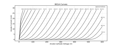
- The 801 / 10 / VT-25 family has a gain of 8x. The 801 can be biased up to 600 V, while the others prefer to not exceed 425 V or so. The gain is a bit lower, but I feel these tubes would be a more practical choice.
Last edited:
i have published boards for 3 versions. original megatron which is 6ca7 current source with 6ca7 output gain tube. (8 x 6ca7 total)
megatronxl 6ca7 current source with 300b as output gain tube. (4 x 6ca7 + 4 x 300b)
optimus prime 300b current source with 300b as output gain tube (8 x 300b)
with 4 x floating current limited switching filament supplies. (needed for the current sources)
power supply for all is +/- 400v.
dc coupled output stage. not exactly cheap.
After some discussion over in the Tube/Valves Forum it looks like the 801 / 10Y / VT-25 tube family is the way to go.Which DHT tubes would be suitable for the output stage?
A neat feature is that these tubes can work well even if the grid is driven positive (Class A2), provided the driver stage can supply the grid current. This allows biasing the tube at a slightly lower anode voltage as compared to the case where the grid voltage must always stay negative (A1). Taking advantage of this, the 10Y / VT-25 can swing +/- 325 Vpk with a 20 mA CCS load and a bias voltage of 440 VDC (curves attached), which is just within their specified limit. In A1, the anode bias would need to be 480 VDC or more, which is okay for the 801, but not for the 10Y / VT-25.
Attachments
Here are some thoughts on the input/driver stage (following up from the list in the first post):
The grids of the output tubes will be biased below the B- / -HV rails, so it would be rather complicated to DC couple the LTP input/driver stage to the output stage. Capacitor coupling works very well, especially if there is no substantial current flowing through the capacitor. Driving the output stage into A2 therefore needs a current buffer. A MOSFET source follower should do the trick.
- Differential amplification from balanced input. I like the long-tailed pair (LTP) for it's symmetry.
- It would be awkward to dilute the DHT sound with a lot of open-loop gain from the input/driver and then apply gNFB. Not gNFB it is!
- Voltage gain:
Single-ended line level is 1.74 Vpk, so balanced input is 2 x 1.74 Vpk
Each of the output-tube grids need to swing 44 Vpk for full output, so the input/driver needs to swing 2 x 44 Vpk Gain = 44/1.74 = 25.4 - The grid current was < 1 mA at +5 V grid, 2 mA at +20 V, and 5 mA at +30 V in my curve measurements shown in the previous post. The drive the output stage into A2, the driver must be able to provide this amunt of grid current.
- Thinking about it, I want some more tubes!
The grids of the output tubes will be biased below the B- / -HV rails, so it would be rather complicated to DC couple the LTP input/driver stage to the output stage. Capacitor coupling works very well, especially if there is no substantial current flowing through the capacitor. Driving the output stage into A2 therefore needs a current buffer. A MOSFET source follower should do the trick.
A folded cascode would be customary in the Stax space. It also allows you to develop far more gain in a single stage. With no NFB, and so much gain, drift could be an issue as it will cause the output stage bias to drift in turn. It could be interesting to load the folded cascode with a gyrator or with a choke, DRD style. Here's an example with a differential current source load, but it will inevitably require a servo or some trimming. Here is the basic idea-- as drawn, it of course will not work.The grids of the output tubes will be biased below the B- / -HV rails, so it would be rather complicated to DC couple the LTP input/driver stage to the output stage.
In the DRD approach, the choke would replace Q3/Q4 and see only the imbalance DC and so would need a minimal gap, while doubling your available voltage swing. You will however need to run double the current with a folded cascode, which, when we're considering a 6E5P and high voltage rails, implies very significant dissipation.
The T2 uses a 700-ish volt shunt regulator (the "active battery") as a level shifter to couple the driver to the power stage. It would work, but it is sort of scary.
I've also built a Stax amp with an interstage transformer load on the output. The whole amp ran off of a single 580V B+, which also fed the bias. With the transformer OPT, it could swing close to double that. So, while it might seem costly, it saved the cost of an additional B- supply and made me feel a bit safer about putting that much voltage right up against my noggin.
")
I also thought about a folded cascode, and I see its advantages if very high open-loop gain is needed. The Stax amps use a lot of gNFB, so the cascode it almost mandatory there. Also, even with gNFB, the Stax amps tend to have a rather high input sensitivity, which means they need a lot of attenuation from a modern line-level source.
As I see it, all we need is a 25x voltage gain. What would be the advantage of a folded cascode compared to the standard anode follower in a long-tailed pair?
As I see it, all we need is a 25x voltage gain. What would be the advantage of a folded cascode compared to the standard anode follower in a long-tailed pair?
Post # 16 Schematic has a Very tricky set-up.
As you said, as drawn, it will not work.
But any drawing with current sources in the co-connected cathodes, and current sources in the plates, will be hard to manage.
1). I-one has to Exactly = ((I-two + I-three) - (Q1 current + Q2 current)).
If it does not, then the quiescent state will have some grid current.
Even if the Equality is met, then If one or more current sources change with temperature, or Q1 or Q2 current changes with temperature . . .
that is another problem.
2). Where is the signal output on that schematic?
3). It is late, I am tired and sleepy, I guess I am missing something on 1). and 2).
That's the charitable way of putting it. With the current sources in series, the only way it will work is if a resistor to ground (or v-) is inserted on the collectors of Q3/Q4, or if some sort of active circuitry adjusts one of the current sources to define the collector voltage. There are a few ways this could be done, but all of them would be complicated and sort of terrible given the limited availability of HV parts. The resistor is not a bad idea, given the modest gain requirement.Post # 16 Schematic has a Very tricky set-up.
The + and - phase outputs are taken from the collectors of Q1/Q3 and Q2/Q4.2). Where is the signal output on that schematic?
My apologies, I missed your gain requirement a few posts up. The big benefit to the folded cascode configuration that I see is that it would enable DC coupling if there's some means of stabilizing the output voltage (servo or gyrator perhaps). But these usually involve a cap and some gain, so perhaps the coupling cap is lesser evil.As I see it, all we need is a 25x voltage gain. What would be the advantage of a folded cascode compared to the standard anode follower in a long-tailed pair?
I'm getting a bit hung up on the grid current requirement on the 801s-- it looks like the curves bunch up quite a bit around +30V on the grid with a 20mA constant current load. If you are looking to take it all the way there with a 44Vpk signal, that puts Va around 250V, which won't be sufficient to hit the 650Vpk design requirement. On the flip side, the 6E5P probably wants to run 15mA+, which would easily meet your grid current requirement were it not for blocking distortion from the coupling cap as you head into positive grid drive. It's also puts the driver stage's dissipation at a significant fraction of that of the output stage. I'd give some consideration to a lower current tube (E180F or EF184 in triode perhaps?) if it will be buffered.
My idea in post #15 was to not drive the 801 grids all the way to +30V. Instead, +5V should be about as much as it gets. To swing the anode voltage by +/- 325 Vpk at 20 mA, the Va bias needs to be 440 V.I'm getting a bit hung up on the grid current requirement on the 801s-- it looks like the curves bunch up quite a bit around +30V on the grid with a 20mA constant current load. If you are looking to take it all the way there with a 44Vpk signal, that puts Va around 250V, which won't be sufficient to hit the 650Vpk design requirement.
I agree that driving the 801 grid into A2 through a coupling cap is asking for trouble. That's why I suggested using a MOSFET source follower as a current buffer to drive the grids. The MOSFET gate would be AC coupled to the input stage via a capacitor.On the flip side, the 6E5P probably wants to run 15mA+, which would easily meet your grid current requirement were it not for blocking distortion from the coupling cap as you head into positive grid drive.
I suggested the 6E5P based on the measured performance I found on the net (as described in post #15), and because its 30x gain is about right.I'd give some consideration to a lower current tube (E180F or EF184 in triode perhaps?) if it will be buffered.
A triode-strapped E180F seems to have about 50x gain, which is on the high end of what we need. There are also some reports that E180F tends to be microphonic.
A triode-strapped EF184 has an even higher gain of 61x (see Pete Millett) and is not as linear as the 6E5P (Moglia).
In the Millett dataset, most lower-power tubes (less than 5 W dissipation) come with higher distortion.
Some other interesting candidates in the Millett list: 8608 (gain 29x) and 12HG7 (39x-50x)
- Home
- Amplifiers
- Headphone Systems
- Open Source DHT Estat Headphone Amp -- OSDEHA