Facepalm moment.
When I looked at the gain of the potential input tubes I assumed a CCS load (gain = mu of the tube). That will of course not work in an LTP differential amplifier, which needs proper anode-load resistors to work. This means the gain will be quite a bit lower than the mu value. The 6E5P may not have enough gain to provide the full swing needed to drive the output stage.
When I looked at the gain of the potential input tubes I assumed a CCS load (gain = mu of the tube). That will of course not work in an LTP differential amplifier, which needs proper anode-load resistors to work. This means the gain will be quite a bit lower than the mu value. The 6E5P may not have enough gain to provide the full swing needed to drive the output stage.
I will look at these again. Is there a way to tell if microphonics might be an issue?I'd give some consideration to a lower current tube (E180F or EF184 in triode perhaps?)
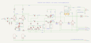
While I am waiting to get some E180F tubes for testing I simply assumed they would be the right choice to go forward. I started to draft a circuit for the full amp (attached). There are some "black-box bloks" in the drawing (I will work on these later):
- The loads for the 801 tubes are the "Gyrator / Hybrid Mu Follower" as conceived by Ale Moglia, see here. Their DC operating point is tied to GND, so the anodes will sit at approximately 0 VDC.
- The buffer FETs ride on a simple 10 mA CCS (probably a single DN2540 shold work fine here). Note that 1 mA will be enough to drive the 801 grid into A2, so I guess 10 mA bias for the buffers should be enough.
Attachments
The E180F tubes arrived, so I could take closer look.
Here are curves in triode mode:
.png")
Looks about right for what is needed in the OSDEHA, maybe with a tiny little bit of compression at high voltage.
I also wanted to know about the reported issues with microphonics, so I hooked them up to the scope and started knocking with a wooden stick. After a while I was pretty decent at knocking in a reproducible way, and this is what it looked like on the scope:

Not knowing if this is good or bad, I also tried an ECC88 (much better):

Or a D3A (also much better):

Or a 6E5P (also much better):

So, overall the E180F has the right curves, but it really is microphonic. Hmmm.
Here are curves in triode mode:
Looks about right for what is needed in the OSDEHA, maybe with a tiny little bit of compression at high voltage.
I also wanted to know about the reported issues with microphonics, so I hooked them up to the scope and started knocking with a wooden stick. After a while I was pretty decent at knocking in a reproducible way, and this is what it looked like on the scope:
Not knowing if this is good or bad, I also tried an ECC88 (much better):
Or a D3A (also much better):
Or a 6E5P (also much better):
So, overall the E180F has the right curves, but it really is microphonic. Hmmm.
If you are using a headphone amplifier, do not knock it.
And . . .
Until proven otherwise, do not bet that all E180F tubes are created equal.
After all, not all 12AX7s are created equal when it comes to microphonics.
And . . .
Until proven otherwise, do not bet that all E180F tubes are created equal.
After all, not all 12AX7s are created equal when it comes to microphonics.
I don't intend to knock the amp in normal use 🙄
Sure, my test was with one single E180F tube only. However, this is just another data point that supports the reported tendency for microphonics with the E180F tube.
The OSDEHA is about high-quality audio reproduction, where noise should be avoided as much as reasonably possible. That's why I am hesitant to use a tube type that has a known tendency for being microphonic.
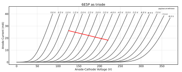
Since I had a tube socket set up for the 6E5P knock tests, I decided to run some 6E5Ps through the curve tracer. I knew they would be linear, and the curve sets are indeed very nice. Also, the voltage gain (mu) of my tubes was slightly higher than what I read elsewhere, which made me reconsider...
Here's a typical curve set with a 12k7 load line, biased to 155 V / 22 mA, showing a +/-44 V swing as needed for the OSDEHA:

The only (small) gripe I have with this solution might be that it comes with a bit more heat than an E180F or an ECC88.
Here's a typical curve set with a 12k7 load line, biased to 155 V / 22 mA, showing a +/-44 V swing as needed for the OSDEHA:
The only (small) gripe I have with this solution might be that it comes with a bit more heat than an E180F or an ECC88.
Attachments
So, overall the E180F has the right curves, but it really is microphonic. Hmmm.
Mind sharing a bit more about your test circuit? I'm guessing we're looking at the plate with the tube in common cathode, at an op point that makes sense for each tube?
I ask because my experience was that the e180f was not particularly microphonic, but I never measured it as you have. I did find them a bit harsh and prone to oscillation in some circuits. I generally ran them at just 2-5mA, much lower than most, and often with a starved heater. Both of these reduce the transconductance (and thus shift the curves, increasing rp) and I believe makes the tube a bit less sensitive to the tap test. Maybe some cathode degeneration would do the same thing? It's not something that I've tried.
The trailing low level high frequency oscillation on the high gm tubes you posted (e180f, d3a, 6e5p) has me wondering if the tubes aren't on the cusp of oscillation. If you want to spend any more time investigating the e180f, I think I'd look into bringing gm down. JC Morisson has an interesting take on the tube here:
https://www.labjc.com/?p=5734
Thanks for sharing these measurements, it's a clever experiment that you designed!
I like the full circuit quite a bit. I would suggest adding a protection zener from G to S on your followers, unless you are confident in the internal protection. I'm also curious about the input coupling caps-- do you think they're necessary?
For the output gyrator-- I tried the J112 IXTP cascode and didn't like it at all when using the mu output. I suspect that the output capacitance of the amp was too high in this configuration. I ultimately switched back to a 10M90S cascode, which sounded better to me, and never figured out the root cause. I'd love to see the gyrator work out.
Sorry, I didn't really explain much. But yes, you pretty much nailed it. My test wasn't super precise and stuff, but it was more than enough to get a good idea. The E180F gave a +/-0.5 mV signal, which would surely be audible.Mind sharing a bit more about your test circuit? I'm guessing we're looking at the plate with the tube in common cathode, at an op point that makes sense for each tube?
Hmm, I didn't think much about if and how gm relates to microphonics. I just thought that the mechanical construction is at the core of how the plate voltage reacts to mechanical vibrations. The ringing frequency seen on the scope is approximately 2 kHz. I'd expect a much higher frequency with electronic oscillation. Anyway, I feel that avoiding microphonic tubes for quality audio is a good idea.I ask because my experience was that the e180f was not particularly microphonic, but I never measured it as you have. I did find them a bit harsh and prone to oscillation in some circuits. I generally ran them at just 2-5mA, much lower than most, and often with a starved heater. Both of these reduce the transconductance (and thus shift the curves, increasing rp) and I believe makes the tube a bit less sensitive to the tap test. Maybe some cathode degeneration would do the same thing? It's not something that I've tried.
The trailing low level high frequency oscillation on the high gm tubes you posted (e180f, d3a, 6e5p) has me wondering if the tubes aren't on the cusp of oscillation. If you want to spend any more time investigating the e180f, I think I'd look into bringing gm down.
The STF3LN80K5 has built in Zeners from G to S. Do you think that external Zeners are needed? My experience with killing FETs is limited, so I don't really know.I like the full circuit quite a bit. I would suggest adding a protection zener from G to S on your followers, unless you are confident in the internal protection.
I am not saying they are always necessary, but I have learned the hard way that some sources do have excessive DC at their outputs. If you know for sure that this is not a problem for a given source, it's easy to skip them.I'm also curious about the input coupling caps-- do you think they're necessary?
Interesting! What amplifier was that (tube types, load)?For the output gyrator-- I tried the J112 IXTP cascode and didn't like it at all when using the mu output. I suspect that the output capacitance of the amp was too high in this configuration. I ultimately switched back to a 10M90S cascode, which sounded better to me, and never figured out the root cause. I'd love to see the gyrator work out.
The switches in my draft circuit are meant to switch between CCS and mu-stage output. What I like about the "gyrator" is that it allows setting the DC operating voltage of the anode. That makes it easy to keep the DC offset between the two anodes close to zero.
The E180F gave a +/-0.5 mV signal, which would surely be audible.
Maybe? 20log(0.0005Vpk/44Vpk) = -78dB. The tube is clearly the most microphonic of the bunch, and I don't mean to suggest you should setle for less than the best, but this might be one of those circuits where you can get away with it.
Hmm, I didn't think much about if and how gm relates to microphonics. I just thought that the mechanical construction is at the core of how the plate voltage reacts to mechanical vibrations.
Transconductance is inversely proportional to the square of the grid-cathode distance. I'd speculate that these high gm tubes, due to their already close g-k spacing, would experience some modulation of their transconductance as the grid sways around the cathode. I'm not sure if this is true or not, but I have found high gm tubes (specifically the 6S45P) are far less microphonic at lower currents, and that tapping them could excite RF oscillation.
The STF3LN80K5 has built in Zeners from G to S. Do you think that external Zeners are needed? My experience with killing FETs is limited, so I don't really know.
My experience with killing FETs is extensive. 🙂 My sense is that an extra zener pays for itself many times over after blowing just one FET.
Interesting! What amplifier was that (tube types, load)?
It's a variation on the Stax SR-X circuit. The driver stage is a 12AT7 cascode LTP cap coupled to a pair of fixed bias gyrator-loaded EL34 triodes. Like you, I thought that using the ground as reference would be a simple way to ensure minimal DC offset (which doesn't particularly matter to the driver, but does matter in that I don't want high voltage on exposed contacts of the amp). Unlike the Stax design, there is no global NFB, allowing the input stage to run higher current and smaller plate loads.
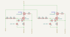
I don't have a schematic of the full amp, but here is the plate load that I used for the output stage. The EL34 ran +/-400V rails and I believe 15mA per tube. It's been some time since I opened it up. 🙂
The multiple series 1M resistors (R4, 5, 6) were to ensure they were run well within their voltage rating and to limit potential stray capacitance/leakage at that node. I don't think I actually built it with the DN2540-- the J112 is pin-compatible (considering D and S are interchangeable).
Looking at my scope shots again, the signal was 0.5 Vpk (not 0.5 mVpk), which would be 20 x log10(0.5/44) = -39 dB.Maybe? 20log(0.0005Vpk/44Vpk) = -78dB.
At 44 Vpk drive to the 801 tubes, I'd expect about 110 to 120 dB-SPL from the headphones, to the "knock" would be about 70 to 80 dB-SPL.
I might do some measurements on the linearity of the E180F and 6E5P to help decide about which tube to choose for the input stage.
Ok, I'll add some Zeners!My experience with killing FETs is extensive. 🙂 My sense is that an extra zener pays for itself many times over after blowing just one FET.
Hmm, ok. Would it be very wrong to use one single resistor of a higher value instead?
The multiple series 1M resistors (R4, 5, 6) were to ensure they were run well within their voltage rating and to limit potential stray capacitance/leakage at that node.
Why did you prefer the J112 over the DN2540?I don't think I actually built it with the DN2540-- the J112 is pin-compatible (considering D and S are interchangeable).
Hmm, ok. Would it be very wrong to use one single resistor of a higher value instead?
So long as the voltage ratings are observed, it should be fine. The resistor to ground will see up to 400V, and the RN55 is rated for a max working voltage of 200V continuous or 450VAC. I prefer to derate aggressively here; if the gyrator fails, the only thing between the user and B+ is a 5k ballast resistor.
Why did you prefer the J112 over the DN2540?
Celebrity endorsements? I think @mogliaa used them. The capacitances of the J112 were a bit lower, which seemed like a good thing. If I were to do it again today, I'd probably look at the RU1C001UN or BSH111BK (also Ale finds) for higher gm and lower capacitances still. It's important to keep capacitance at the output low or you lose the efficiency that's gained from using an active load in the first place, as the headphone load is basically a small capacitor itself.
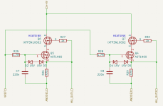
Here's my current draft of the "dual gyrator" load for the 801 tubes.
Very good point. I'll change that accordingly in my draft.The resistor to ground will see up to 400V, and the RN55 is rated for a max working voltage of 200V continuous or 450VAC. I prefer to derate aggressively here; if the gyrator fails, the only thing between the user and B+ is a 5k ballast resistor.
Makes sense. However, I'd like to stick to through hole parts for this project. @mogliaa recommended the AOT1N60 and IXTP3N100D2 parts for this (see here and here).
Attachments
To take a deeper look at E180F vs 6E5P I measured their harmonic distortion in a plate-follower configuration at Ia = 10 mADC and Vg = -3 VDC. I used cathode bias, with a bypass capacitor across the cathode resistor. B+ was always at 440 VDC, as used in the OSDEHA. The measurements show a 10 Vrms output of the 1 kHz fundamental.
Here's the E180F:

And the 6E5P:

Both are nice, but the 6E5P is nicer. Note that much of the even-order harmonics will cancel in the differential input stage, while the odd-order will add up and are therefore more critical. With the E180F, the 3rd harmonic is down by 78 dB relative to the fundamental, while with the 6E5P the 3rd is 99 dB below the fundamental. The 6E5P is pretty impressive!
During these tests I also observed that linearity is worse if the grid is biased closer to the cathode. Vg = -2.5 VDC already showed higher 3rd harmonic.
Conclusion: the 6E5P it is!
Here's the E180F:
And the 6E5P:
Both are nice, but the 6E5P is nicer. Note that much of the even-order harmonics will cancel in the differential input stage, while the odd-order will add up and are therefore more critical. With the E180F, the 3rd harmonic is down by 78 dB relative to the fundamental, while with the 6E5P the 3rd is 99 dB below the fundamental. The 6E5P is pretty impressive!
During these tests I also observed that linearity is worse if the grid is biased closer to the cathode. Vg = -2.5 VDC already showed higher 3rd harmonic.
Conclusion: the 6E5P it is!

Just for reference here are the harmonics of the 6E5P at different grid bias points.
6E5P at B+ = 440 V, Ia = 10 mA, Rk = 28k, Vg = -3 V
(same as in previous post)

6E5P at B+ = 440 V, Ia = 10 mA, Rk = 34k, Vg = -2 V
(shows higher 3rd and higher harmonics)

6E5P at B+ = 440 V, Ia = 10 mA, Rk = 28k, Vg = -3 V
(same as in previous post)
6E5P at B+ = 440 V, Ia = 10 mA, Rk = 34k, Vg = -2 V
(shows higher 3rd and higher harmonics)
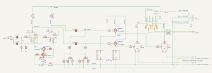
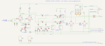
Here's an updated draft for the amplifier circuit, including the "gyrator" loads and the CCS for the buffer FETs:
- I changed the input tubes and their bias point as described in the previous posts.
- The "gyrator" loads are inspired by the work of @mogliaa, but with two "gyrators" running in parallel, using GND as a voltage reference instead of a current source.
- The buffer CCS are just the usual DN2540 depletion FET.
- I added a film/foil cap from the buffer gate bias voltage to B- with the aim to reduce noise at this point.
Attachments
Looks great! I don't think you need to change anything to get great sound or reliable operation, but here are some what-if ideas to play with.
If you're so inclined, you could replace the 6E5P plate load resistors (R4 and R9) with the same dual gyrator that you are using on the output stage with a suitable 160V reference-- perhaps an LND150 into a zener string. At DC, it won't fight with the tail CCS as the gyrator defines a static voltage rather than a static current.
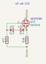
If you would like to double your parts count for questionable improvement, here's the circuit that I used for my tail CCS. It's based on the Gary Pimm self bias CCS, and the general idea is that using a very large source resistor will increaase the CCS impedance significantly. I don't know that it will actually make a difference here, but I do think that with 400V to burn, it's worth considering what will give you the most bang for your watt. I like that this method sets the current more repeatably; it could be useful to do something like this for your MOSFET followers with a shared voltage reference, so that the two run at similar currents without a trimpot. The attached schematic is for 40mA rather than 20mA, because I misread your post. 🙂
It also looks like you have a fairly wide adjustment range on your fixed bias supply. With an active load and fairly cold biasing on the DHTs, I'd see if I could get away with no trimming at all; the voltage can't drift, and current drift will need to be significant before anyone's in trouble.
If you're so inclined, you could replace the 6E5P plate load resistors (R4 and R9) with the same dual gyrator that you are using on the output stage with a suitable 160V reference-- perhaps an LND150 into a zener string. At DC, it won't fight with the tail CCS as the gyrator defines a static voltage rather than a static current.
If you would like to double your parts count for questionable improvement, here's the circuit that I used for my tail CCS. It's based on the Gary Pimm self bias CCS, and the general idea is that using a very large source resistor will increaase the CCS impedance significantly. I don't know that it will actually make a difference here, but I do think that with 400V to burn, it's worth considering what will give you the most bang for your watt. I like that this method sets the current more repeatably; it could be useful to do something like this for your MOSFET followers with a shared voltage reference, so that the two run at similar currents without a trimpot. The attached schematic is for 40mA rather than 20mA, because I misread your post. 🙂
It also looks like you have a fairly wide adjustment range on your fixed bias supply. With an active load and fairly cold biasing on the DHTs, I'd see if I could get away with no trimming at all; the voltage can't drift, and current drift will need to be significant before anyone's in trouble.
Attachments

That's what I thought of, too. However, the long-tailed pair (LTP) differential input stage needs proper ohmic load resistors. If the grid of the left tube swings positive, the current through that tube decreases. The CCS tail forces the right tube to balance the current by a corresponding increase. The output voltages taken from the anodes are controlled by Ohms law that converts the current variations through the anode resistors to a voltage signal. See also here for a detailed explanation of the LTP. With a gyrator load that works as a CCS in the AC domain, there would be no AC current swings that could be mirrored between the tubes by the tail CCS, so the LTP would not work as intended.If you're so inclined, you could replace the 6E5P plate load resistors (R4 and R9) with the same dual gyrator that you are using on the output stage...
That's an interesting suggestion, but yes, it does add more parts. I am trying to not make the whole thing bigger than necessary. How much "better" would the more complex CCS be for the LTP tail?If you would like to double your parts count for questionable improvement, here's the circuit that I used for my tail CCS. It's based on the Gary Pimm self bias CCS, and the general idea is that using a very large source resistor will increaase the CCS impedance significantly. I don't know that it will actually make a difference here, but I do think that with 400V to burn, it's worth considering what will give you the most bang for your watt.
That's intentional. The idea is to keep the whole thing relatively flexible to allow using slightly different tubes (801, 10Y, VT25). But yes, maybe the range is larger than needed. I'll look into this.It also looks like you have a fairly wide adjustment range on your fixed bias supply.
Last edited:
Ok, looking at the curves measured with my 801 and VT25 tubes the biasing would work out like this for +/-325 Vpk swing at 20 mA idle, with grid voltage swinging up to +5 V:It also looks like you have a fairly wide adjustment range on your fixed bias supply.
- 801 tubes want to bias at 440 V / 20 mA, which is -40 V at the grid
- VT25 tubes want to bias at 425 V / 20 mA, which is -35 V at the grid
Ok, one more draft before I continue working on the power supply, and on the PCB layouts. Changes relative to the 090224 version:
- Removed the DC blocking input caps from the amplifier board. The amplifier board assumes a proper balanced input without any DC. Running the input from the chassis sockets to the DC blocker caps on the amplifier board, then to the volume pot, and back to the amplifier board results in unnecessary long signal wires. It makes more sense to move the DC blockers near the volume pot (and yes, the DC blockers may not even be necessary for a balanced input).
- Tweaked the range of the grid bias adjustment as discussed before.
Attachments
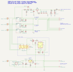
Here's first draft for the power supply.
Here's a breakdown of the different sections (starting at the bottom):
Here's a breakdown of the different sections (starting at the bottom):
- The DC supply for the heaters of the input-stage tubes is nothing fancy. Just a full-wave rectifier followed by an LM1085 to get 6.3 VDC for the heaters. The heaters of the 6E5P tubes take up to 0.65 A each. There are two 6E5P per channel (four for stereo), so we need about 2.6 A in total. The Coleman filament regulators for the DHT filaments are on separate boards, so they are not shown here.
- On top of the DC rides a delay circuit that turns on the B+ and B- supplies a few seconds after the heaters are up. The circuit is inspired by the delay used in the High-Amp AC amplifiere (see here). It's 555 timer with 1MΩ + 22uF RC element controls a relay that turn on the transformer secondaries of the B+ and B- supplies.
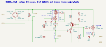
- The high-voltage supplies (see separate drawing) for the B+, B-, and buffers/grid-bias are inspired by a circuit shown by @mogliaa (see here). It is a relatively simple concept using a CCS for a stable voltage reference (2 x LND-150 cascode). The voltage drop across the "RSET" resistor is buffered by ZTX560 BJT and applied to the STF5NK100Z FET that outputs a smooth DC. There are many other schematics/concepts for HV PSUs out there, but they usually rely on a feedback mechanism for regulation of the output voltage. This may provide excellent measured performance, but a PSU without feedback regulation tends to provide better sound in my experience.
- The bias voltage for the headphone stator is inspired by the Golden Reference HV PSU (see here). It's basically a "charge pump" from the transformer secondary AC riding on the B+ DC output. When the AC swings negative and falls below the DC voltage derived from the B+, the B+ supply charges the capacitor connected to the AC secondary. Once the AC starts swinging positive again, the capacitor charge is pumped through the 10M90S and into the tail of the circuit, where the voltage is limited to 580 VDC by the Zener string.
Attachments
- Home
- Amplifiers
- Headphone Systems
- Open Source DHT Estat Headphone Amp -- OSDEHA