This means if my OB lower point will be 100 Hz then, maximum D must be less than 0.5*3.44=1.72 m. I my first simulation U-frame depth is at maximum 0.4 m.Gerrit Govaerts
The U-frame can be used as long as you stay both under the cavity resonance and the D/lambda<<0.5 constraint (with D=dipole distance , lambda=wavelength )
I have used MJ King's calculations here http://www.quarter-wave.com/OBs/U_and_H_Frames.pdf for my U-frame Subs, I don't know how this calculator compares Cavity Resonance
In your OP, it looks like there's a "K-coupler" style slot at the top of your enclosure.
I've wondered if such a feature would be useful in a wall (or two) of a U frame? Perhaps allowing one to approach that 1/4 wave cavity resonance of an equivalent size structure - without the K slots - more closely. Instead of being restricted to 1/4 - 1/3 of the 1/4 wave frequency, maybe you could go all the way to 1/2?
Anyway - whatever - I just wanted to let you know I noted that feature in your design.
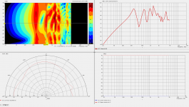
I added polar plot on distance of 1 m to Akabak simulation in my first post. This is OB half U-frame half L-frame. Max depth is 40 cm on one side, on shorter side panel is asymmetrically placed (little like Karlson) slot.
Slot side is on -90 deg.
Slot side is on -90 deg.
Attachments
Last edited:
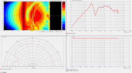
When on 400 mm deep U-frame side panel is only Karlson type slot and symmetrically, then result is very different. Slot side is on -90 deg.
Attachments
Last edited:
kaamelis, there must be something fundamentally wrong with your AKABAK sim. Your sims have this 200/300Hz peak/dip that must be an artefact - it happens at all angles!
Attachments

Last edited:
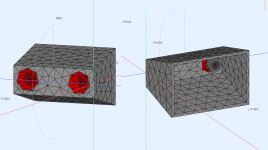
I am not 100% sure I made simulation correctly but 2D baffle you compare my results is very different. My U-frame had depth 400 mm what is close to planar baffle with radius of 2x400 mm. I add also image of uncut U-frame, front panel 200x600 mm, rear opening 400x600 mm, depth 400 mm, rear opening is wider than front panel, 200 mm vs 400 mm.
The biggest peak is probably cavity resonance (on top of dipole peak) what you cannot simulate in Edge.
The biggest peak is probably cavity resonance (on top of dipole peak) what you cannot simulate in Edge.
Attachments
Last edited:
OK, so it seems. But DR and those AC guys have the top open so the lowest mode around 300Hz is not happening!
amroc - THE Room Mode Calculator
amroc - THE Room Mode Calculator
Room mode calculator did not give accurate result for this U-frame as it missing back wall and side walls are not parallel.
Generally Edge cannot be used to simulate any OB what has 3D structure, it can be used only for simulating plane baffles.
Generally Edge cannot be used to simulate any OB what has 3D structure, it can be used only for simulating plane baffles.
If you have the drivers I'd suggest to knock something up and have a play, that's what the guru DR did, hopefully you won't be so reluctant to post measurements 😉
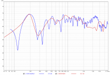
I had mad this already. Here is comparison with real OB speaker measurements and AKABAK simulation responses of same OB with front panel 200x600 mm, rear opening 400x600 mm, depth 400 mm. Actual measurement is made in room, gated within 12 ms, but still room modes influence the result at lower than 400 Hz, also probably enclosure material resonances as it is made for testing and is not resonance fee.
Now I am searching what cuts can be done on U-frame to get flat response.
I added also Akabak simulation file, if somebody find error in it, pleas let me know.
Now I am searching what cuts can be done on U-frame to get flat response.
I added also Akabak simulation file, if somebody find error in it, pleas let me know.
Attachments
Last edited:
It's important where the nulls are as well, it will help when it comes to placement in your room.
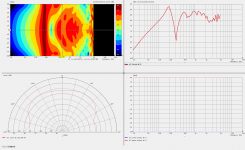
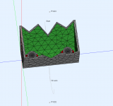
I made new simulation. Basically same OB with U-frame as in post Open baffle MTM questions only side panels are cut with sawtooth pattern.
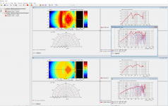
For comparison is made 2 versions, lower curves on image had internal part U-frame side of panels (geern on image) defined with wall impedance damping coefficient 0.5. Upper is same but without damping.
On image observation point C1 is located on rear side, 1 m from front panel, C2 is on front side, 1 m from panel.
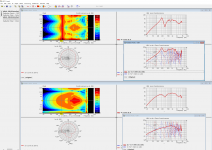
From simulation I can make conclusion that big part of peak at 200 Hz is from U-frame cavity resonance.
So question is: How do damp specifically 200 Hz peak on U-frame rear part?
For comparison is made 2 versions, lower curves on image had internal part U-frame side of panels (geern on image) defined with wall impedance damping coefficient 0.5. Upper is same but without damping.
On image observation point C1 is located on rear side, 1 m from front panel, C2 is on front side, 1 m from panel.
From simulation I can make conclusion that big part of peak at 200 Hz is from U-frame cavity resonance.
So question is: How do damp specifically 200 Hz peak on U-frame rear part?
Attachments
Last edited:
I'm not sure you can make that conclusion. It could be the damping is effecting the diffraction. Also as Juha said, it could be an artifact?From simulation I can make conclusion that big part of peak at 200 Hz is from U-frame cavity resonance.
It's good to see the nulls, is that where you want them?
Why?
If I look rear side measurements on damped version, there is no peaks but on forward side measurement is visible null on 350 Hz. Generally panel diffraction contribute about 6 dB, minimum on 350 Hz is about 10 dB.
If I look rear side measurements on damped version, there is no peaks but on forward side measurement is visible null on 350 Hz. Generally panel diffraction contribute about 6 dB, minimum on 350 Hz is about 10 dB.
Last edited:
Did I understand diffraction wrong, if I interpret it on speakers in way that diffraction is happening with radiation of same speaker cone side. If front cone side response is affected with radiation from rear side of cone then it is called dipole pekas and miniumums.
- Home
- Loudspeakers
- Multi-Way
- Open baffle MTM questions