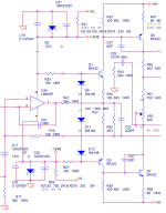
yes my biggest fear is assembling one without a pcb, one mistake and the whole thing goes to waste. or making a mistake in the pcb
yeah theyre absolutely overkillThat is not many parts 🙂
Haven't you seen some designs on this forum? They are crowded!
thats what i want to buildYou mean designs with 250 current mirrors in them? Makes sense on ICs where transistors are essentially free, and inherently matched. Not so much with packaged discretes.
There isn’t any reason why you can’t…. There could be a list as long as your arm why you shouldn’t. But you could also claim that every one of those reasons doesn’t apply/doesn’t matter here. And you wouldn’t really be wrong.
Just determine what parts you can commit the project, and go ahead and build hardware. The costliest part of this is the case, power supply and heat sink. Which can be re-used if it doesn’t meet expectations.
Just determine what parts you can commit the project, and go ahead and build hardware. The costliest part of this is the case, power supply and heat sink. Which can be re-used if it doesn’t meet expectations.
Actively bootstrapped op-amp to allow high output voltage for a regular op-amp, see PDF in @EUVL's post:
You can actually bootstrap 15V opamps to higher rail voltages.
Please read this carefully and understand first before trying.
If you design your own PCB with SMD, you might even fit this onto a DIP8 adaptor.
Patrick
.
Please read this carefully and understand first before trying.
If you design your own PCB with SMD, you might even fit this onto a DIP8 adaptor.
Patrick
.
You essentially bootstrap the entire opamp alone with the internal compensation network. If you don’t want to deal with the stability rabbit hole, don’t do that.Actively bootstrapped op-amp to allow high output voltage for a regular op-amp, see PDF in @EUVL's post:
is it the same rabbit hole if bootstrapped from the power amp output?the stability rabbit hole
such as here: https://www.diyaudio.com/community/threads/ez-dump-dump-your-current-without-really-trying.263065/
i tried making it i only made the output stage and it does ffunny things becuse of some error in the assembly process, i should make an pcbDoes it work.
Is LT1056 a good opamp?
In the right hand panel select the "Objects" tab and click on the eyeball looking thing next to "Values". You can control the display of most items in that panel.im trying to make a pcb in kicad but i cant seem to get rid off this gray text,
There is a KiCad forum that can be helpful:
https://forum.kicad.info/
Also the "Getting Started" manual will be most useful:
https://docs.kicad.org/8.0/en/getting_started_in_kicad/getting_started_in_kicad.html
yeah it gets annoying i should practice making pcbsThat don't look nice 🙁
Don't give up - making pcbs can be a lot of fun!gets annoying
Apologies if this is a basic or confusing question, but I'm having trouble understanding how the voltage of ±35V to ±80V in an amplifier circuit can be reduced to safe levels for an opamp, like the NE5534, which has a wide supply voltage range of ±3V to ±20V. Which components or part of the circuit are responsible for lowering the voltage to levels that allow the opamp to operate safely?
- Home
- Amplifiers
- Solid State
- OpAmp as Input in Power Amplifier - exploration
