I guess the good news is this should work electrically. Maybe you could read some articles and watch some videos on PCB layout and get a better feel for how to make a 'nice layout.'does that look better?

Peavey got away from the TL071/72/74 in about 2000 and went to the NJM4580. Slightly better on noise IMHO and perhaps more durable when roadies plug a 30 w guitar amp speaker output into the line level jack. Peavey still clamps the input to the op amp power supplies with diodes and uses a 1000 ohm 1/10 w series resistor to burn out in that case, instead of a $1.50 fuse. Evidence CS800x and CS800s products. I do not know why Peavey did not use the even cheaper NE5532, whose main datasheet disadvantage is higher supply current.Also, I'd be inclined to use the NE5534, instead of the TL071. It's significantly better in most respects and costs very little.[/quote}
As you got the chance to design it by yourself, you should let the opamp work in class A (single ended) by any chance. A good looking symmetry circuit might not suggest good performance.

i have the njm4580 in a sip package i actually found two, theyre from a sony mini system i gutted.Peavey got away from the TL071/72/74 in about 2000 and went to the NJM4580. Slightly better on noise IMHO and perhaps more durable when roadies plug a 30 w guitar amp speaker output into the line level jack. Peavey still clamps the input to the op amp power supplies with diodes and uses a 1000 ohm 1/10 w series resistor to burn out in that case, instead of a $1.50 fuse. Evidence CS800x and CS800s products. I do not know why Peavey did not use the even cheaper NE5532, whose main datasheet disadvantage is higher supply current.
Some thoughts of mine:copied the schematic to kicad to make making the pcb easier. EDIT: i forgot about the input capacitor
View attachment 1378326
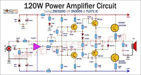
- Replace the diode string D1 through D4 as well as RV1 and R9 by a bias spreader (Vbe multiplier) with a thermally coupled transistor.
- TIP41 and TIP42 yet are slowish devices. They get even more slowed down when arranged as Darlingtons. It's better to replace R7, R8 by a single resistor between both driver emitters.
Best regards!
or just use integrated darlingtons. i also dont want to use a vbe multiplier here becuse id have to plug the op amp in a weird way
That “weird way” also results in better raw op amp performance…..if you’re talking about hanging it to the negative rail. The only thing that won’t let you do is double boot strap.
could i use an darlington for thermal coupling? it seems that i can buy 3 tip12x transistors for quite cheap but i need to buy three
The TIP12x aren’t the best darlingtons for thermal compensation because of those darn base emitter resistors. You really don’t want them there in a vbe multiplier. They might be ok if the values were an order of magnitude or two higher. But 30 to 100 ohms is just plain wrong.
With this old circuit I built my first real amplifier in the early 70s with my first homemade circuit board.
It is still there and works. I used 2N3055 as output transistors.
The IC is of course long outdated, but can sometimes be found as NOS.

It is still there and works. I used 2N3055 as output transistors.
The IC is of course long outdated, but can sometimes be found as NOS.
Attachments
built the output stage out, it runs really hot becuse of the transistors (tip122) (tip125) internal biasing resistors or othe components. 2 diodes should be enough to bias them and thermal runaway and the feedback loop should take care of the rest.
My contribution Using OPA552 OpAmp 60 volt
Using Boot Strapped Diamond Buffer so no VBE multiplier needed and auto bias.
No additional voltage drops or VBE is needed for outputs since CFP
It is close to 60 to 65 Watts into 4 Ohms. So I have included 2 output pairs for low distortion and relentless drive into 4 ohms.
For proper stability and current sharing this would be example for parallel output CFP.... YES the extra resistors are needed.
Including Degen resistors R11 and R10 and Current sharing R13,16 ,17,18.
T1 through T4 are thermally linked and T5 T6 T7 T8 ARE NOT in that Thermal Loop like Darlington. If your worried about runaway
they wont, bias is from the Diamond and increasing Degen R11 and R10 to only 2.7 or 3.3 ohms will have more control of the outside thermal behavior

20 kHz Square wave 3 ohm load


25 watts 8 ohm
THD 1 kHz = .0008 %
THD 20 kHz= .005 %
25 watts 4 ohm
THD 1 kHz = .0009 %
THD 20 kHz= .008 %
65 watts 4 ohm
THD 1 kHz = .0024 %
THD 20 kHz= .012 %

10 kHz Square Wave 5 Vp 10 Vpp 4 ohm load
Slew Rate 11.6 V/us

Using Boot Strapped Diamond Buffer so no VBE multiplier needed and auto bias.
No additional voltage drops or VBE is needed for outputs since CFP
It is close to 60 to 65 Watts into 4 Ohms. So I have included 2 output pairs for low distortion and relentless drive into 4 ohms.
For proper stability and current sharing this would be example for parallel output CFP.... YES the extra resistors are needed.
Including Degen resistors R11 and R10 and Current sharing R13,16 ,17,18.
T1 through T4 are thermally linked and T5 T6 T7 T8 ARE NOT in that Thermal Loop like Darlington. If your worried about runaway
they wont, bias is from the Diamond and increasing Degen R11 and R10 to only 2.7 or 3.3 ohms will have more control of the outside thermal behavior
20 kHz Square wave 3 ohm load
25 watts 8 ohm
THD 1 kHz = .0008 %
THD 20 kHz= .005 %
25 watts 4 ohm
THD 1 kHz = .0009 %
THD 20 kHz= .008 %
65 watts 4 ohm
THD 1 kHz = .0024 %
THD 20 kHz= .012 %
10 kHz Square Wave 5 Vp 10 Vpp 4 ohm load
Slew Rate 11.6 V/us
He is using low Ft transistors MJE2955/3055 in post #125the thd dosent seem that impressive too
That is almost Full Power at 10 kHz not 1 kHz
so THD .01 % is actually rather dam good.
You dont know what your looking at
THD at 1 kHz would be likely .006 %
With basic transistors and TL072 opamp your amp wont do more than .1% at 10 kHz full clean power
He is showing high frequency at high power.
Little different ball game than THD1 at 1 watt ratings
Here is the impressive one. No bias current at output stage, because it is current dumping. Output 10Vp to 8 Ohm.that kinda misses the point of simplicity. the thd dosent seem that impressive too
Note, with LM358.
Last edited:
- Home
- Amplifiers
- Solid State
- OpAmp as Input in Power Amplifier - exploration