There is enough feedback there that the entire distortion floor is determined by EM compatibility alone.
And the lead compensation is absolutely required. With “large” output stages that type of amp works better with the lead comp (C4) taken off the VAS instead. That produces other fringe benefits besides stability with rugged slow output trannies. I always end up with lower levels of crossover distortion.
And the lead compensation is absolutely required. With “large” output stages that type of amp works better with the lead comp (C4) taken off the VAS instead. That produces other fringe benefits besides stability with rugged slow output trannies. I always end up with lower levels of crossover distortion.
no harm in changing the models of said components also this topology is used in one kitI like to see a simple but good one with common parts like NE5532 & TIP3055.
View attachment 1376062
EDIT: here is the kit
link to buy it: https://sklep.lampyelektronowe.pl/?1442,rs-simpleamp-zestaw-do-samodzielnego-montazu
and here is an video:
Last edited:

am i one of the reasons for this thread? its just what i need right now, thanks @lineupThis thread is about all ways to use OpAmp as input stage in power amplifiers.
Let us see your way to do this.
There are many ways to make an opamp control a power amplifier.
There are good ways, I am sure - and less good ways.
I have one way up my sleeve now, but I also have Choctaw in another thread.
What is the purpose of Q3/Q4? A current source to put the opamp into Class A? If so, why not attach that to Pin 6?no harm in changing the models of said components also this topology is used in one kit
EDIT: here is the kit
link to buy it: https://sklep.lampyelektronowe.pl/?1442,rs-simpleamp-zestaw-do-samodzielnego-montazu
and here is an video:View attachment 1376253
Gain of the op amp's output stage, cascode and output MOSFETs at fixed at 11, so together with the front end of the op amp, this is more like a composite amp. Nice! No compensation needed except for C1?
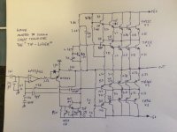
I like to see a simple but good one with common parts like NE5532 & TIP3055.
Oh, you want TIPs? I’ll give you TIPs.
The problem with common cheap transistors is getting them to run on Enough Voltage To Do Something With. Hope you’ve got enough room for all those emitter resistors.
It’s tonge-in-cheek, but at the same time, it’s not. I did this with MJ21193/4 and took the supply voltage from the ridiculous to the sublime. It works. That prototype went to a symmetric front end, no reason to go that far with TIPs and only +/-60V. The KM442 (+/-75V) did use the TIP mod in the VAS so it’s been verified.
Attachments

I just doubt it can drive an 8 ohm load with significant voltage ...classic
i replaced the bd140/139 with mje2955/3055 and the 150ohm with an 220ohm. preferably i would use an opa552 and faster transistor. the opa is a good op amp for this choice due to its high slew rate of 24V/µS, high supply voltage and high output current. another idea would be to run them "hot" which should make the threshhold voltage lower.

here is an photo of to notch with this circuit, barely visible.
here is an photo of to notch with this circuit, barely visible.
I like the topology with opamp front ends. It's an easy way to get very high OLG in a simple design. I've wanted to explore some ideas myself.
Attachments
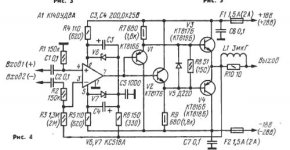
Here's a relatively simple poweramp from the Siliconix applications handbook, 1985 -

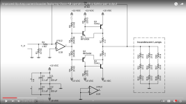
Here is a relative simple AD847 amplifier.
It is driven by the opamp's supply rails..
The distortion is very low.
It can use more voltage than +/-25V, of course.
It took 4 compensation capacitors to get it stable.
Phase Margin is good. 86 degrees.

It is driven by the opamp's supply rails..
The distortion is very low.
It can use more voltage than +/-25V, of course.
It took 4 compensation capacitors to get it stable.
Phase Margin is good. 86 degrees.
Well, it is optimized for minimal parts count. Note the nested feedback that restricts gain in the output stage to about 5.That one is beautiful @abraxalito
And with TL071 simply.
I don't think the TL071 will take kindly to having its supply bounce around. Two extra transistors for cascoding the supply lines will both keep the 071 happy, increase bandwith of the output stage and enable higher rail voltages.
thats cool. i should build it.Here's a relatively simple poweramp from the Siliconix applications handbook, 1985 -
View attachment 1376425
Maybe consider a transnova topology as per Hafler, Chevin and some QSC amps. The main compromise is two power supply windings are required. One per channel. The advantage is that the output stage can operate at a higher voltage since it doesn't require rail voltage driving.
Attachments
The double power supply requirement is a non starter for most. Single transformers that can do this cost a manufacturer only a few bucks extra. For DIY it’s double, or more. You either buy two and live with the weight or pay through the nose, out the rear end, and all the way to the bank for a custom wind.
If it weren’t for that transnova would probably have taken over completely, as it is typically far simpler.
If it weren’t for that transnova would probably have taken over completely, as it is typically far simpler.
- Home
- Amplifiers
- Solid State
- OpAmp as Input in Power Amplifier - exploration