In my very little reading I saw that the TD160's suspension was or could be a pain to "tune". One poster wrote that on suspended wood flooring walking was a problem. Your problem sounds severe. I'm thinking you are being very careful once you drop the needle. Low volume level and still cone huffing..? Some questions might be what environment the TT is in? How mounted? Does the TD160 + Linn Basik S-shaped arm have a reputation for mechanical sensitivity/feedback? What is the model # of the Grado cart? Do you have a scope?
This might be relevant:
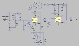
C8 can better be a film capacitor and R1, R2 and R6 can be replaced with one 47 kohm resistor to ground when the supply is symmetrical. C3 and R5 are then also superfluous if you can allow a few millivolts of offset.
Hi all,
While thinking about ways to speed up the settling of a single-supply single-op-amp RIAA amplifier, see https://www.diyaudio.com/community/...upply-phono-preamp-design.413571/post-7702435 , I found a way to include a second- or third-order Butterworth high-pass filter. As it may be useful outside the context of single-supply circuits, I give it a separate thread.
When you just look at the topology and ignore the component values, this is a rather conventional RIAA amplifier (you could make it even more conventional by connecting R7 in...
- MarcelvdG
- Replies: 176
- Forum: Analogue Source

C8 can better be a film capacitor and R1, R2 and R6 can be replaced with one 47 kohm resistor to ground when the supply is symmetrical. C3 and R5 are then also superfluous if you can allow a few millivolts of offset.
Of course I could redesign it for 15 Hz or 18 Hz or whatever and for a cartridge requiring a low load capacitance.
When I say use the DC servo for rumbling is that very low frequency that I am thinking about. Would it be possible to adjust the servo to cut say below 5Hz?
When you do that straightforwardly, just change the time constant of the DC servo and precorrect the first RIAA pole, it will work, but you get only a first-order roll-off. You will then again need a cut-off frequency of 33.4 Hz to get 16.6 dB of suppression at 5 Hz, just like with your 100 nF capacitor.
I think there are ways to make it second-order Butterworth, which would result in the same 16.6 dB suppression of 5 Hz with only 12.93 Hz cut-off frequency and a very flat response in the audio band, but it will require an extra AC coupling capacitor somewhere and a weird dimensioning of the servo loop. Give me a day or two and I'll see if I can come up with something.
Last edited:
I also recommend OPA192 as the best for DC servo, = less than 1 microvolt @ phonopreamp output DC and no electrolytes at all [ https://c10.patreonusercontent.com/...=SPSa43vN9tw-MzZMVPZjhrAyz75s5Ae6QxtfWq_6j9Q= ]The OPA192 was recommended to me as being as low noise as the OPA1656, but with very low offset. It simulated quite well.
Last edited:
may be also decrease C7 ?an extra AC coupling capacitor somewhere and a weird dimensioning of the servo loop
Am I correct in thinking that a DC servo with two poles could not be stable?
Much thanks, as always,
Chris
Much thanks, as always,
Chris
Last edited:
Not necessarily. If both poles are in the origin, it would need a left-half-plane zero to become stable. If one of the poles is negative real and in the feedback path, it causes a negative real zero in the input-to-output transfer that you can correct for with a first-order high-pass elsewhere (hence my remark about the AC coupling somewhere).
may be also decrease C7 ?
There is no C7 in the schematic attached to carlmart's post #213 (the one with a DC servo op-amp).
I meant circuit in your post #223There is no C7 in the schematic attached
I will use the LF411, which I have a few of, for the DC servo, which will be on a separate proto pcb board. The one Borbely used on all his discrete preamps.
You might remember that this preamp project will be assembled on two different Aliexpress boards, where I will change the discrete parts of. I will open a threat with all the operating details.
Changing the on-board supplies will be the most laborious work of this all, as I intend to replace the original supplies with the Denoisator supplies developed on another thread of this forum. Look which the regulators will be.

I finished the complete schematic late last night and still need to double and triple check everything. I will go with a single transformer and rectifier for the sake of simplicity (as I mentioned, not aiming for ultra-high-end).

There are two RIAA boards I will be using, both being two stages.
The passive one is quite straightforward and probably easier to modify. The space used by the dual 3X7 supplies to be used to place a four-supply board, two for each channel. The Denoisator supplies does accept sharing the supplies between channels.
The active one already uses four separate regulators and pre-regulators, one for each channel left and right. The regulators they use here are two 7X18 followed by two 7X15, which I want to improve for noise and impedance. Same as above's. Which is what the Denoisator does.
I was considering using Wal Jung Superregulators, but space used would be too much, and cost would be much higher. Besides, being more "agressive" to achieve minimum noise and lower impedance makes the Superregulators more critical.
So that's a sum-up of the whole project.
You might remember that this preamp project will be assembled on two different Aliexpress boards, where I will change the discrete parts of. I will open a threat with all the operating details.
Changing the on-board supplies will be the most laborious work of this all, as I intend to replace the original supplies with the Denoisator supplies developed on another thread of this forum. Look which the regulators will be.
+12 and +5 rails use LM317s and -12 rail uses a LM337. Quite standard setup I guess.You will be using just 317s, or 337s too?
I finished the complete schematic late last night and still need to double and triple check everything. I will go with a single transformer and rectifier for the sake of simplicity (as I mentioned, not aiming for ultra-high-end).
There are two RIAA boards I will be using, both being two stages.
The passive one is quite straightforward and probably easier to modify. The space used by the dual 3X7 supplies to be used to place a four-supply board, two for each channel. The Denoisator supplies does accept sharing the supplies between channels.
The active one already uses four separate regulators and pre-regulators, one for each channel left and right. The regulators they use here are two 7X18 followed by two 7X15, which I want to improve for noise and impedance. Same as above's. Which is what the Denoisator does.
I was considering using Wal Jung Superregulators, but space used would be too much, and cost would be much higher. Besides, being more "agressive" to achieve minimum noise and lower impedance makes the Superregulators more critical.
So that's a sum-up of the whole project.
That discrete preamp is practically the same as the one I was going to build, based on Luxman 5C50 and Luxman L10 preamp stages. They were pure DC and didn't use a DC servo. The input stage was very very stable, and you did zero offset with a trimpot, when you saw the drift LED lighting on. Which rarely happened, so stable it was.I also recommend OPA192 as the best for DC servo, = less than 1 microvolt @ phonopreamp output DC and no electrolytes at all [ https://c10.patreonusercontent.com/4/patreon-media/p/post/70903013/03fe6365d5ee4ef482986f29d24c3a09/eyJxIjoxMDAsIndlYnAiOjB9/1.jpg?token-time=1740355200&token-hash=SPSa43vN9tw-MzZMVPZjhrAyz75s5Ae6QxtfWq_6j9Q= ]
I abandoned that project.
Attachments

Last edited:
lie, it's not "pure DC" due to the separating capacitor C 110 at the outputThey were pure DC and didn't use a DC servo.
Marcel,
Would you suggest any changes that could improve things on the second, Erno Borbely based on design, be it on the RIAA and/or the DC servo.
I wonder if the DC servo can also work as a rumble filter. If you increase or decrease the servo output resistor also decreases or increases the preamp THD. But I wonder if it's not altering the RIAA filter too.
When you change the topology to this:
and change the values of some components as indicated in this list:
R10: 40 kohm or 47 kohm? The original has 40 kohm, but 47 kohm is the usual value.
CX: 470 nF
RX: 33.2 kohm
R9: 1740 ohm
R3: 487 ohm
RA: 56.2 kohm
CA: 56 nF
R5: 6.19 kohm
R4: 39.2 kohm
R8: 23.2 kohm
you have a Borbely-style RIAA amplifier with a second-order Butterworth high-pass at 13.36 Hz, giving more attenuation at 5 Hz and below than your 100 nF input coupling capacitor would. Due to capacitive voltage division between CX and C3, there is a gain reduction of about 0.83 dB.
I'll get back to redimensioning the amplifier of posts #222 and #223 later.
I have checked the opamps I have here, and I've got 10 each of OPA637 and OPA627, which seems a good place to start from.
Plenty of AD797s too, but seems to be a bit unreliable for
Plenty of AD797s too, but seems to be a bit unreliable for
No lie, you could go around the C110 cap. That amp always gave you that option. The amp owner did, as the Luxman showed when there was DC offset.lie, it's not "pure DC" due to the separating capacitor C 110 at the output
In any case most amps have an input cap at the following stage. In fact it would be wise to bypass one and leave just the input cap. One designer suggested to eliminate all output caps in an integrated amp and leave just the one in the power amp input, and then replace that cap with a high quality one.
And if I do not use the servo? I have ask. Do I change the parts anyway?When you change the topology to this:
View attachment 1419457
and change the values of some components as indicated in this list:
R10: 40 kohm or 47 kohm? The original has 40 kohm, but 47 kohm is the usual value.
CX: 470 nF
RX: 33.2 kohm
R9: 1740 ohm
R3: 487 ohm
RA: 56.2 kohm
CA: 56 nF
R5: 6.19 kohm
R4: 39.2 kohm
R8: 23.2 kohm
you have a Borbely-style RIAA amplifier with a second-order Butterworth high-pass at 13.36 Hz, giving more attenuation at 5 Hz and below than your 100 nF input coupling capacitor would. Due to capacitive voltage division between CX and C3, there is a gain reduction of about 0.83 dB.
I'll get back to redimensioning the amplifier of posts #222 and #223 later.
There's any discrete part you don't quite agree with?
I don't understand what you mean. I thought you wanted to add a subsonic filter to the circuit of post #213, preferably using the DC servo for that, but with a steeper than first-order response. The best solution I can come up with for that is as shown in post #234.
Anyway, the value of R9 in the original circuit makes no sense. It should be 1.6 kohm, or 1.58 kohm if it has to be an E96 value. I also don't understand why R10 is 40 kohm rather than 47 kohm (or 47.5 kohm if it has to be an E96 value).
Anyway, the value of R9 in the original circuit makes no sense. It should be 1.6 kohm, or 1.58 kohm if it has to be an E96 value. I also don't understand why R10 is 40 kohm rather than 47 kohm (or 47.5 kohm if it has to be an E96 value).
Last edited:
I do not want to use a 100n or any capacitor at the input. I was interested in curing the flapping with a servo, not with a cap.When you change the topology to this:
View attachment 1419457
and change the values of some components as indicated in this list:
R10: 40 kohm or 47 kohm? The original has 40 kohm, but 47 kohm is the usual value.
CX: 470 nF
RX: 33.2 kohm
R9: 1740 ohm
R3: 487 ohm
RA: 56.2 kohm
CA: 56 nF
R5: 6.19 kohm
R4: 39.2 kohm
R8: 23.2 kohm
you have a Borbely-style RIAA amplifier with a second-order Butterworth high-pass at 13.36 Hz, giving more attenuation at 5 Hz and below than your 100 nF input coupling capacitor would. Due to capacitive voltage division between CX and C3, there is a gain reduction of about 0.83 dB.
I'll get back to redimensioning the amplifier of posts #222 and #223 later.
Even adding the 100n input cap, a 1st order filter, puts me -17dB @ 20Hz, not good at all.
From what I read in this and other forums, what I called the "flapping" is a 3Hz frequency. So I simulated a servo just on 1st stage, using the Borbely RIAA as seen.
I think it got me good results. Apparently, with the values I adjusted looking at the FR curve, -3dB @ 20Hz and -27dB @ 3Hz and other low frequency noise garbage.
What do you think? Am I right on my sims?
Attachments
Yes, but the FR curve turned out not to be steep enough. So I redesigned with the new servo values to get closer to what I wanted. Just tell me if I did something wrong, please. You do know more about RIAA poles than I do.I don't understand what you mean. I thought you wanted to add a subsonic filter to the circuit of post #213, preferably using the DC servo for that, but with a steeper than first-order response. The best solution I can come up with for that is as shown in post #234.
Anyway, the value of R9 in the original circuit makes no sense. It should be 1.6 kohm, or 1.58 kohm if it has to be an E96 value. I also don't understand why R10 is 40 kohm rather than 47 kohm (or 47.5 kohm if it has to be an E96 value).
I will adjust R9 value as per your suggestion. And sorry about the input cap and resistors values. According to Grado, the resistor must be 47K and the cap 100p. They are corrected. Next I will correct R9. Sorry I saw your comments after sending my answer.
- Home
- Source & Line
- Analogue Source
- OPA1656 Phono Preamp: Split from OPA1656 thread