OK, the LT1792 had caught my attention from another project that used it, and I was looking for a bifet opamp to replace the AD745, that was difficult to implement on an existing pcb and was way too expensive. It was also low noise. But you are right on the offset and slew rate.
Particularly offset is a mystery really, as it seems to be a habit of some LT opamps I tried that I now perceive they do not show any voltage offset. It seems it's not part of their opamps models, is it?
Even if I have the option of the OPA627 and OPA637, that I have a few of, swapping for other opamps to listen which sounds better it's an interesting option to have. So the OPA164x and OPA165x seem good options to try.
Now I wonder why the thread project is using the 165x instead of the 164x? Have they been listened to or actually measured?
Can't comment on the Vos spec of LT parts. Haven't used those op amps. I wouldn't go crazy searching for ultra-low voltage and/or current noise for this RIAA pre. The LP surface noise will swamp most/all steady state op amp noise - don't you think? I mean, just look at the super strict low noise suggestions for possible applications of the 1792. Don't need that if it doesn't sound good. 😊
I found that in that circuit and in my system the OPA627 turned my head. I had to agree with all the good things I had read. It's just "clean". And to some of the same extent so did the OPA2107. And once the bad behavior of the OPA1656 coupled with my TT was solved by a man on this forum it was OK and nice but it didn't win the contest. I bought eight pieces of OPA1642 mounted on DIP8 carriers and rolled them into my system mains/sub cross-over some time ago.
The "listeners" I have paid attention to don't care much for specs. They plug them in, listen and compare and contrast and judge, etc. Can't measure this stuff.
In the older data sheet for the difet 1641/42 you will see for the first time the same RIAA phono preamp application that was lifted and placed into the 2019 CMOS OPA1656 data sheet by the Project Manager I think purely as a proud marketing thing vs. sonics. It certainly has the DNA for the job. Also in the OPA1641/42 sheet is a graph of the flat difet input capacitance over + and - common mode voltages vs. the typical variance in biFET gate capacitance. That was the new BB difet effect.
The OPA192 was recommended to me as being as low noise as the OPA1656, but with very low offset. It simulated quite well.
Also tried the OPA828, that is relatively low offset and has lower noise than the OPA1656. Plenty of OPAs to have a listen to, with output caps or DCservo.
Also tried the OPA828, that is relatively low offset and has lower noise than the OPA1656. Plenty of OPAs to have a listen to, with output caps or DCservo.
Look out with DC servos and RIAA amplifiers, don't let them shift your poles unless you precorrected them!
Hi all,
I sometimes see people trying to put DC feedback loops around phono preamplifiers. When you put a DC servo loop around a phono preamplifier, the feedback shifts the poles, particularly the lowest one, and may mess up the RIAA correction accuracy. One way around that is to deliberately shift the correction network poles such that they end up where they should be with the DC servo loop closed. I did some calculations about that, see the attachment. I hope it will be of use to someone.
Best regards,
Marcel

Plenty of OPAs to have a listen to, with output caps or DC servo.
I hope you meant WITHOUT ....
No, I mean that depending on the chip you use, most of them show DC offset that you have to block or stop. Either using a feedback cap that has to be large and electrolytic, an output DC film cap or a DC servo to compensate the offset.
One of the few lowest offset opamps I simulated, the OPA828, puts out 50mV.
One of the few lowest offset opamps I simulated, the OPA828, puts out 50mV.
Last edited:
As both DC servos are based on a Walt Jung RIAA passive design, and the other on a Erno Borbely discrete preamp, my guess is they pre-corrected the servos, haven't they?Look out with DC servos and RIAA amplifiers, don't let them shift your poles unless you precorrected them!
Hi all,
I sometimes see people trying to put DC feedback loops around phono preamplifiers. When you put a DC servo loop around a phono preamplifier, the feedback shifts the poles, particularly the lowest one, and may mess up the RIAA correction accuracy. One way around that is to deliberately shift the correction network poles such that they end up where they should be with the DC servo loop closed. I did some calculations about that, see the attachment. I hope it will be of use to someone.
Best regards,
Marcel
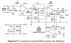
Here's the Walt Jung two-stage passive preamp with DC servo, as published by AD here:
https://www.analog.com/media/en/training-seminars/design-handbooks/Op-Amp-Applications/Section6.pdf
https://www.analog.com/media/en/training-seminars/design-handbooks/Op-Amp-Applications/Section6.pdf
Attachments
In this preamplifier, https://audioxpress.com/article/from-the-vault-the-borbely-preamp , the DC servo in the first stage is harmless, the one in the second stage shifts the first RIAA correction pole. Fortunately, the DC servo in the second stage is so slow that the pole only shifts by a negligible amount.
Marcel,
Would you suggest any changes that could improve things on the second, Erno Borbely based on design, be it on the RIAA and/or the DC servo.
I wonder if the DC servo can also work as a rumble filter. If you increase or decrease the servo output resistor also decreases or increases the preamp THD. But I wonder if it's not altering the RIAA filter too.
Attachments
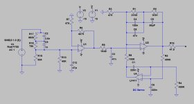
It does alter the RIAA correction. When you decrease R8, you increase the bandwidth of the servo loop. Besides increasing the high-pass corner frequency of the servo, that also increases the shift of the first RIAA correction pole.
Besides, you have to keep the parallel value of R3 and R8 constant to keep the RIAA correction zero at the right place.
If you want to increase the servo loop bandwidth so much that it becomes a useful subsonic filter, the shift of the first RIAA correction pole will become quite substantial. You can either precorrect the pole position such that it ends up where it should be after the shift, or add a zero in the DC servo that lies on top of the first RIAA correction pole to keep it from shifting.
The first method is inconvenient when you want to make the cut-off frequency of the subsonic filter switchable. You would also have to switch the RIAA correction network then, because each bandwidth setting requires its own precorrection.
I'll think about an elegant way to implement the second method. If I find something potentially useful, I will post it.
Just prior to the arrival of carlmart I was about to blend-in a continuation of my journey with the single-stage RIAA EQ box which proved kinda interesting in a cone-bottoming way and in short, contributed to by many and solved by Marcel. But this time I was interested in a hopefully more elegant approach to my current trouble with sub-sonic "room slosh". I had a whole first post prepared but now I wonder if the subject belongs somewhere else or here (since the subject did arise) or what. I figured all the original players would get a "new post" email and come to read or, maybe not. Comments..?
It's up to you, but if you want to keep it well-organized, you could start a new thread and link to it here, so that everyone here gets notified about its existence.
Thanks Marcel.It does alter the RIAA correction. When you decrease R8, you increase the bandwidth of the servo loop. Besides increasing the high-pass corner frequency of the servo, that also increases the shift of the first RIAA correction pole.
Besides, you have to keep the parallel value of R3 and R8 constant to keep the RIAA correction zero at the right place.
If you want to increase the servo loop bandwidth so much that it becomes a useful subsonic filter, the shift of the first RIAA correction pole will become quite substantial. You can either precorrect the pole position such that it ends up where it should be after the shift, or add a zero in the DC servo that lies on top of the first RIAA correction pole to keep it from shifting.
The first method is inconvenient when you want to make the cut-off frequency of the subsonic filter switchable. You would also have to switch the RIAA correction network then, because each bandwidth setting requires its own precorrection.
I'll think about an elegant way to implement the second method. If I find something potentially useful, I will post it.
What I have observed on my Thorens TD160 + Linn Basik S-shaped arm + Grado cartridge with a discrete preamp that I was using was what I called a very low frequency "flapping" of the woofers when playing LPs.
My guess is it was 1 to 5 Hz, because you could see the woofer move not linearly. What I did on that preamp was add a 100n input polystyrene, which controlled the flapping.
More recently I saw the same "flapping" on another system much more sophisticated than mine: a Thorens TD-150 with better straight Linn Basik arm, using a Shure V-15 cartridge, through a Luxman 5C50 pure-DC phono preamp, state of the art even today. I captured an LP that was never released in CD. Then I processed it digitally to clean all the spikes. The result was magnificent.
The "flappings" didn't show in the captured FR as spikes or anything.
When I say use the DC servo for rumbling is that very low frequency that I am thinking about. Would it be possible to adjust the servo to cut say below 5Hz?
That's exactly where my thread continuation was going to here goes>>>>
Since I last posted I still have the low-gain tube preamp w/o phono (Schiit “Freya+”) and now have low sensitivity speakers (ELAC Carina FS-247.4 floor-standers). The w/o phono input prompted me to build the TI OPA1656 datasheet RIAA phono preamp in the first place back in ’21 and there’s some history to that. But, the combo of the Freya’s 12dB tube preamp gain and the 86-87dB speakers caused me to crank-up the preamp to satisfactory levels but with that came some sub-sonic “room-slosh” feedback, sensitivity to foot-drops and so on. I tried to bolster the TT’s isolation and that took care of a lot but I could just feel things going amok with my R & L 18” passive down-firing subs and a third sub added in the rear-center (SVS SB-1000) where I could feel the cone pumping. Once triggered it just goes round and round – self-perpetuating sub-sonic energy.
Note: The Mains and the Subs are crossed with a state-variable, LR-4, 24dB/oct 2-way at ~70hz.
So what I did was to add a lot of crap to my TI datasheet RIAA EQ circuit. The front end had to be a Zin=47K buffer in order to receive the cart then drive the 3rd-order, 18Hz S-K high pass then on to the nice clean OPA627 RIAA section. So that’s two new additional op amp stages – albeit good ones.
The 3-stage arrangement does work. The room slosh is gone/controlled. The 3rd order @18Hz doesn’t allow the low-freq feedback room slosh to get hold - to then be boosted further by the RIAA +20dB. But I think it could be cleaner.
What I would like is a minimalistic front-end 2nd or 3rd order subsonic filter that mates with a 4-5mV MM cart, does its thing and then drives a very high-Z RIAA EQ circuit. And b/c of the Freya’s low gain, if easily done I would also like more gain in, or for the equalized output (i.e. >40dB @1000Hz) possibly within the EQ circuit itself. I’ve tried to reduce the 127R gain R but doing so jacks-up the in-series C. So first question is can one add R in the feedback loop without upsetting the RC time constants?
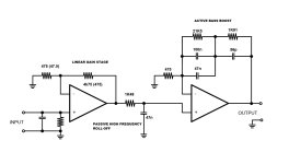
I’d love ideas. Maybe a RC passive high-pass up-front? I do strongly want to preserve 30Hz and above. The attached is the detail the filter I built and the rough overall sketches. (Please forgive my crayon-quality dwgs. I’m too old and/or lazy to learn a drawing package.)
Since I last posted I still have the low-gain tube preamp w/o phono (Schiit “Freya+”) and now have low sensitivity speakers (ELAC Carina FS-247.4 floor-standers). The w/o phono input prompted me to build the TI OPA1656 datasheet RIAA phono preamp in the first place back in ’21 and there’s some history to that. But, the combo of the Freya’s 12dB tube preamp gain and the 86-87dB speakers caused me to crank-up the preamp to satisfactory levels but with that came some sub-sonic “room-slosh” feedback, sensitivity to foot-drops and so on. I tried to bolster the TT’s isolation and that took care of a lot but I could just feel things going amok with my R & L 18” passive down-firing subs and a third sub added in the rear-center (SVS SB-1000) where I could feel the cone pumping. Once triggered it just goes round and round – self-perpetuating sub-sonic energy.
Note: The Mains and the Subs are crossed with a state-variable, LR-4, 24dB/oct 2-way at ~70hz.
So what I did was to add a lot of crap to my TI datasheet RIAA EQ circuit. The front end had to be a Zin=47K buffer in order to receive the cart then drive the 3rd-order, 18Hz S-K high pass then on to the nice clean OPA627 RIAA section. So that’s two new additional op amp stages – albeit good ones.
The 3-stage arrangement does work. The room slosh is gone/controlled. The 3rd order @18Hz doesn’t allow the low-freq feedback room slosh to get hold - to then be boosted further by the RIAA +20dB. But I think it could be cleaner.
What I would like is a minimalistic front-end 2nd or 3rd order subsonic filter that mates with a 4-5mV MM cart, does its thing and then drives a very high-Z RIAA EQ circuit. And b/c of the Freya’s low gain, if easily done I would also like more gain in, or for the equalized output (i.e. >40dB @1000Hz) possibly within the EQ circuit itself. I’ve tried to reduce the 127R gain R but doing so jacks-up the in-series C. So first question is can one add R in the feedback loop without upsetting the RC time constants?
I’d love ideas. Maybe a RC passive high-pass up-front? I do strongly want to preserve 30Hz and above. The attached is the detail the filter I built and the rough overall sketches. (Please forgive my crayon-quality dwgs. I’m too old and/or lazy to learn a drawing package.)
Attachments
carlmart,
What I think you are describing as cone flapping is a Arm/Cartridge resonance coupled with probably some room feedback "slosh" which tends to perpetuate or re-excite the resonance. If at all so, the TT's position has to be isolated from the room. The series input C of 100nF + the 47K cart load created a very roughly 6dB/oct @34Hz high-pass filter - driven by the complex innards of the cart. In my mind a musical sub-sonic filter must preserve at least 30Hz and up (i.e. 4-string bass, 5-string bass, the double stand-up bass, pipe organ and so on). 20Hz and up would be ideal. One has to be careful b/c low-order filters have a long reach. FWIW. Hope I wasn't off-base.
What I think you are describing as cone flapping is a Arm/Cartridge resonance coupled with probably some room feedback "slosh" which tends to perpetuate or re-excite the resonance. If at all so, the TT's position has to be isolated from the room. The series input C of 100nF + the 47K cart load created a very roughly 6dB/oct @34Hz high-pass filter - driven by the complex innards of the cart. In my mind a musical sub-sonic filter must preserve at least 30Hz and up (i.e. 4-string bass, 5-string bass, the double stand-up bass, pipe organ and so on). 20Hz and up would be ideal. One has to be careful b/c low-order filters have a long reach. FWIW. Hope I wasn't off-base.
OK, we agree on 20Hz being the lower point to aim to. I won't be using any cap at the preamp input, that's why I was considering (and willing to try) using a servo for one or both stages, and adjust the servo capacitors until the resonance in arm/cartridge is tamed down.
How would you propose to isolate the TT from the room? That would be the first thing I would attack.
My aim with this come back to my turntable is to capture digitally all my LP collection, using a Tascam DR-70D @ up to 24bit-96KHz or less. The Tascam's preamps certainly have input caps, so putting a cap at the RIAA preamp output wouldn't be necessary. But that doesn't mean I will let out anything DC, except up to 20uV or so.
I won't be using the TT, after this capture is done, to listen to music. LPs and tapes were very fragile media, in spite of being even better than the first and second generation of digital recording. They were also very unpractical and a pain to use.
- Home
- Source & Line
- Analogue Source
- OPA1656 Phono Preamp: Split from OPA1656 thread