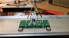
2sj74
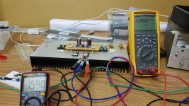
15Vds
Ids = 6.9mA
Degeneration.......................Id (mA)
0 Ohms...............................6.92 mA
4.010 Ohms.........................6.00 mA
10.095 Ohms.......................5.00 mA
15Vds
Ids = 6.9mA
Degeneration.......................Id (mA)
0 Ohms...............................6.92 mA
4.010 Ohms.........................6.00 mA
10.095 Ohms.......................5.00 mA
Probably going to set the source trimpot at 16 Ohms, 4 Ohms, for 2sk170/2sj74 respectively, as a starting point.
Using Jfets with Idss of around 7mA for 2sj74 and 10mA for 2sk170.
Once I have confirmed source trimpot values, I may replace with fixed resistors. I have catered for the use of either a trimpot or through hole resistors in that position.
Using Jfets with Idss of around 7mA for 2sj74 and 10mA for 2sk170.
Once I have confirmed source trimpot values, I may replace with fixed resistors. I have catered for the use of either a trimpot or through hole resistors in that position.
Last edited:
Yeah.
It gives me more headroom to play around with biasing and rail voltages.
I am not particularly interested in trying to copy a circuit that is Nelaon's IP.
It gives me more headroom to play around with biasing and rail voltages.
I am not particularly interested in trying to copy a circuit that is Nelaon's IP.
Last edited:

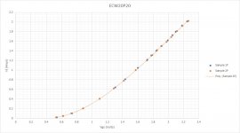
Mosfets measured for amp.
Maybe I should comment about some of this.
1) You will see the lateral mosfets are excellent matching parts. I didn't test 10 parts to get this level of matching, all of them in the tube match this well. These are just the first two of each that I measured.
2) Looking at the curves - In order to hit 2A on each part, I need 1.6V and 2.25V at the gates of the N channel and P Channel parts respectively.
3) Based on my previous jfet testing of Id vs Degeneration, with a 16/4 Ohms setting on the trimpot, we have an Id current of roughly 6mA for each jfet (probably closer to 6.5mA on 2sk170). In order to reach a max bias of 2A, using the previous Vgs values (see [2] above) we need R = 2.25/0.006 = 375 Ohms at the drain of 2sk170 to bias up the P Channel Mosfet (we need less for the N Channel mosfet).
I will therefore use a 200 Ohm trimpot in series with a 200 Ohm resistor. Depending how I feel, I may use a 150 Ohm resistor instead.
Last edited:
where is your bloody sense of adventure ......... nothing exciting when you plan everything up front

matched this, matched that , yada yada .......

matched this, matched that , yada yada .......
Hahahahaha
I hate desoldering parts.
I promise you it has nothing to do with being a nerd and everything to do with avoiding desoldering.
This amp is such a bastard to be honest. It looks so elegantly simple but it's not really, the J2 is far simpler. The bloody Vgs threshold mismatch between N and P in the most inconvenient way, is the bastard here.
This just proves I am a bloody dumb bastard. Hahahahaha
Last edited:
btw. nothing wrong with decent (cermet track) trimpots ...... even Pa is using them as permanent parts , so why not
ZM being Chicken , I'm always using multiturns .... easier on my faint Heart
🙂
ZM being Chicken , I'm always using multiturns .... easier on my faint Heart
🙂
Last edited:
I am using multiturn. hahahaha
It's just that they are 200 Ohm multiturns so I am adding a series resistor. I have made space on the pcb for a series resistor or solder in a link.
It's just that they are 200 Ohm multiturns so I am adding a series resistor. I have made space on the pcb for a series resistor or solder in a link.
Yeah.
I reckon I spend more time thinking about how to avoid making mistakes than if I just made a bloody ton of them and fixed them on the fly.
I reckon I spend more time thinking about how to avoid making mistakes than if I just made a bloody ton of them and fixed them on the fly.
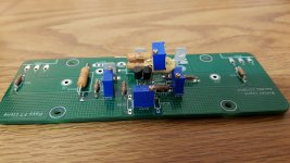
Trimpot operation
Bias Control
Anticlockwise increases bias current
Jfet source resistance
Clockwise: reduces source resistance at 2sj74.
Bias Control
Anticlockwise increases bias current
Jfet source resistance
Clockwise: reduces source resistance at 2sj74.
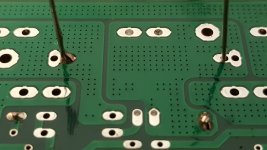
...Probably going to remove these faston connectors as I won't be using them. ....
Evil things, they are.
- Home
- Amplifiers
- Pass Labs
- On A Hippie Trail, Head Full Of Zombie