I knew it was a ground but only stumbled on the work around. Using one of the empty 0v from the psu board works and seems like a much better solution. Thank you.
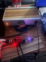
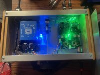
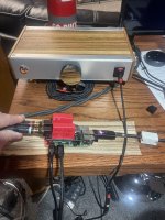
Another Omicron up and running! Unlike many of my builds that remain "unchassis'ed" (part lazy, part lack of skill, part "on to the next thing"......!) I went ahead and buttoned this one up. Sounds really good! Dead quite! Just started messing with Raspberry Pi, DAC HAT (ProtoDac) and streaming. THANK YOU to Alexcp for sharing and making boards available! I post even less than I fully finish projects (diy thing I guess?) so hopefully I have not screwed anything up? High time to participate and more importantly THANK the greater diyaudio community for all the knowledge, willingness to share, help, and inspire! Not possible without this community! THANK YOU!
Ed
Ed
Attachments

Ed,
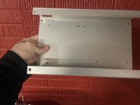
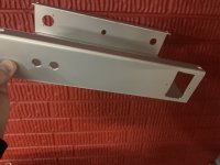
I really like your case, I was going to use the same technique. I am glad you did it and it works, and looks great. How did you bend the aluminum? Last time I bent it I had to cut a groove on the backside, was a little difficult to get table saw depth just right.
Thanks
Bill
I really like your case, I was going to use the same technique. I am glad you did it and it works, and looks great. How did you bend the aluminum? Last time I bent it I had to cut a groove on the backside, was a little difficult to get table saw depth just right.
Thanks
Bill
Thanks Bill!
Full disclosure...............I cheated! Here!
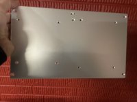
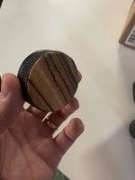
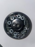
I thought it was a fair price for the the amount of time and effort for sourcing, bending, cutting, and potentially/unnecessarily screwing that part of it up. Fit and finish of the pieces/parts as arrived were fantastic. I did my best not to butcher my part. It was very easy to cut, drill (stepped bit for larger holes), counter sink and it is built like a tank. The bottom/top plate I had to cut length-wise to fit into the recess as it overlapped the width? I didn't like the look of just all aluminum top so I veneered with some scrap I had laying around. My cut was not perfect so there is just a slight gap but it allows some of the LED light from under the hood the shine through and I think that is cool? Volume knob is a "ribbed" juice bottle lid that I epoxied in a traditional volume knob. Drilled a small hole for the set screw access and epoxied in nuts and bolts to add weight. Added the matching veneer and now it almost looks legit.....don't tell anyone it is a cheap juice bottle lid!
Ed
Full disclosure...............I cheated! Here!
I thought it was a fair price for the the amount of time and effort for sourcing, bending, cutting, and potentially/unnecessarily screwing that part of it up. Fit and finish of the pieces/parts as arrived were fantastic. I did my best not to butcher my part. It was very easy to cut, drill (stepped bit for larger holes), counter sink and it is built like a tank. The bottom/top plate I had to cut length-wise to fit into the recess as it overlapped the width? I didn't like the look of just all aluminum top so I veneered with some scrap I had laying around. My cut was not perfect so there is just a slight gap but it allows some of the LED light from under the hood the shine through and I think that is cool? Volume knob is a "ribbed" juice bottle lid that I epoxied in a traditional volume knob. Drilled a small hole for the set screw access and epoxied in nuts and bolts to add weight. Added the matching veneer and now it almost looks legit.....don't tell anyone it is a cheap juice bottle lid!
Ed
Attachments
Ed,
Very creative, I love seeing solutions outside the box. Helps open my mind to alternative solutions. Just soldered up smd version , was putting it off but turned out quite fun using hot air. Mouser shorted a few parts so will have to wait to finish up. Case will accommodate my hiby docking station on top of it, trying to tidy the nightstand.
Bill
Alex,
Is there any sonic difference between the through hole vs smtp ? I was thinking due to heat dissipation you had to lower the bias on the smtp version.
Is there any sonic difference between the through hole vs smtp ? I was thinking due to heat dissipation you had to lower the bias on the smtp version.
Electronic circuits don't have sonic anything! You have to be careful with SMT parts, for instance thin-film(*) resistors are required for low-distortion, and its best to choose larger sizes even so. Polypropylene (PP) and polystyrene (PS) caps aren't available (they melt in a reflow oven), so you probably want to pick PPS caps which are reasonably good performers. Surface mount can be much better thermally BTW due to heatpads directly soldered to the PCB - with multilayer boards in 2oz copper the PCB is an effective heatsink.
Is SMT metal film is called thin film, and metal oxide is called thick film, just to be confusing.
Is SMT metal film is called thin film, and metal oxide is called thick film, just to be confusing.
It's more like the TH version can have much higher bias if needed, esp. with taller heatsinks, while in the SMT version is limited by the heatsinking provided by the PCB itself. Stock TH runs at about 50mA (with 100 ohm resistors), while SMT runs at about 25mA.you had to lower the bias on the smtp version.
In principle, the lower biased output stage would leave Class A sooner with large signal peaks and a low-impedance (32Ω) load. Class A ends at twice the quiescent current, so for the SMT board with its 25mA, that would be 50mA, or 80mW into 32Ω. With a typical can sensitivity of 100dB/mW and a normal listening level, that would happen from time to time, but not very frequently. However, Omicron stays very, very linear even when that happens (see the bottom of post 11).
In practice, I find it hard to hear any difference even with my 32Ω Grado GS1000i.
That's true, and the BOM includes all the right stuff. Only thin film resistors and NP0/C0G (white-blue, not brown) capacitors in the amp proper and MKP caps in the crossfeed circuit. The protection circuit does use brown 1uF X7R caps, but these don't matter. Also, quality, low(ish) ESR electrolytic caps are recommended for both TH and SMT versions - but nothing exotic; the prototype uses Panasonic FC throughout.You have to be careful with SMT parts
In the end it is a great build (the smt) parts were very easy to source and build was much quicker than through hole (for me). I would highly recommend it for project for learning to solder smt.
Bill
Bill
I'd be happy to but am not sure there is enough interest at the moment. Let me know if I'm wrong 😉
Hi everybody,
may I kindly request if is it possible to buy the pcbs, parts, etc. in a kit?
Best regards and thanks,
Francesco
may I kindly request if is it possible to buy the pcbs, parts, etc. in a kit?
Best regards and thanks,
Francesco
may I kindly request if is it possible to buy the pcbs, parts, etc. in a kit?
There is no kit, but, for a fee, Alex may put together a SMD board for you, if he still has boards and parts, of course.
From there, building the power supply and case work is relatively easy.
Hi ElArte,
Thank you very much for your prompt reply.
Would you, please, be so kind to introduce myself to Alex or let me know how to contact him to make a "new Omicron user" happen?
Thanks again and best regards,
Francesco
Thank you very much for your prompt reply.
Would you, please, be so kind to introduce myself to Alex or let me know how to contact him to make a "new Omicron user" happen?
Thanks again and best regards,
Francesco
Any replacement for murata 78602/3MC?
Doesn't have to match the footprint. Digikey is out of the question for ordering at my place.
3JC is a possible replacement, if 180uH is fine instead of 200uH?
Doesn't have to match the footprint. Digikey is out of the question for ordering at my place.
3JC is a possible replacement, if 180uH is fine instead of 200uH?
Last edited:
Not at the moment - unless someone wants to part with the boards from an earlier GB and put together a kit for you.if is it possible to buy the pcbs, parts, etc. in a kit
In a way of explanation, Omicron (at least its through-hole version) was designed to be inexpensive and simple to build with garden variety parts, most of which you probably already have, and the rest, easily obtainable from the usual sources.
78602/3JC is a direct replacement. Other 1:1:1 transformers from the same 78602/xJC series should work. As a last resort, you can probably wind your own on a ferrite core - I have not tried, but why not? Wind with three wires simultaneously and use each of the three as a separate winding. You don't need many turns as long as the leakage inductance is in the hundreds on nH range.murata 78602/3MC
Hi Alex and Hi everybody,
If anybody is interested to sell the pcb's, components, or already assembled parte, I am interested in that.
Thank you very much and best regards,
Francesco
If anybody is interested to sell the pcb's, components, or already assembled parte, I am interested in that.
Thank you very much and best regards,
Francesco
- Home
- Amplifiers
- Headphone Systems
- Omicron, a compact headphone amp with -140dB distortion