This should be self-explanatory:

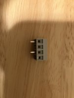
It doesn't matter which pin in "N" and which is "L", either way is good. Three holes/pads on the board are to accommodate both 2x 3.96mm and 2x 5.08mm connectors, and the two overlapping pads on the right on your photo are (obviously) internally connected.
Do not omit/forget the jumpers that set the mains voltage. On this photo, two red jumpers set 120VAC. For 240VAC, there should be one jumper between the two middle contacts on the green (gray on your board) terminal block - the while silkscreen next to the terminal block, partially visible on your photo, shows the correct connection.
Last edited:

I started testing the power supply with a 43 watt dim bulb. When I powered it on, the led did light up, but the dim bulb never did. I didn’t take any measurements, I turned it off. There was no smoke or strange noises.
Is it safe to proceed?

Is it safe to proceed?
I moved on to finish up the amp board and forgot about the pin sockets for U1 and U21, I soldered them directly to the board. How much trouble is that going to cause?
I'm not an expert, but I would assume the bulb didn't light up because the PSU is low current, especially with no load. For the amp board, some might argue that directly soldered opamps are superior to sockets, you are fine to solder them directly to the board, but will have more difficulty in the future should you decide to try a different opamp.
I have built an SMT board with NE5532, and one with OPA1642, and to be honest I am not sure I can identify any differences in sound.
I have built an SMT board with NE5532, and one with OPA1642, and to be honest I am not sure I can identify any differences in sound.
PCBs for Alps RK27 are sold in a number of places including the diyAudio store.
https://diyaudiostore.com/collections/misc-pcbs/products/rk27-breakout-pcb
https://diyaudiostore.com/collections/misc-pcbs/products/rk27-breakout-pcb
Thank you @bloqhed and @ItsAllInMyHead!
The bulb lights up if the transformer's primary draws a large current. This usually indicates that the (power) amp draws lots of current from the secondary winding, or, in the case of a single flash on power-on, that the bulk filter capacitors are being charged. Unlike a power amp's, this power supply is (a) low current, as @bloqhed pointed out, and (b) doesn't have large inrush current because of the small (=relatively high impedance) transformer and the two filter resistors in the primary circuit. So the bulb would light up only if the primary winding is miswired, which is unlikely because it's all on the PCB.the led did light up, but the dim bulb never did
@bloqhed is right - nothing bad happens, just rolling opamps may be difficult. Desoldering an 8-pin package from a plated-through board is fairly easy with a hot air gun, but hard with a soldering iron.forgot about the pin sockets for U1 and U21
I used a piece of FR4 rod from McMaster-Carr.6mm aluminum rod
Thank you for the explanation @alexcp, I’ll leave things as is. I think I’ve spent almost as much in shipping costs as actual parts! Living and learning and enjoying this build.
I used a piece of FR4 rod from McMaster-Carr.
I'll have to bookmark that for when I run out of the aluminum I have, light weight and sturdy is key, I didn't think about FR4, it's very light and very strong.
hi, i need some advice/help.
i've almost finished 'my' Omicron amp+psu. i've started matching bd139/140-16 devices (based on hfe readings), but i'm unsure what to do next.
bd139 hfe is 150 (+-5 out of 100pcs) bd140 is 180 (+-2 out of 10pcs).
what is awaited hfe for this devices (and do they need to be matched closely ?? )
thx for help 🙂
I have been thinking about ways to heatsink the output transistors on the SMT board, so that I could increase the bias current. Would picking up some thermal tape, and sticking these heatsinks on each output transistor be a viable solution?
Right now I am biased with 68ohm in R13, R14, R33, R34 as per the BOM. Assuming the above linked heatsinks are viable, what would be a suggested value to swap in for the bias resistors?
Right now I am biased with 68ohm in R13, R14, R33, R34 as per the BOM. Assuming the above linked heatsinks are viable, what would be a suggested value to swap in for the bias resistors?
Those are cool heatsinks!
The quiescent current and the dissipation are roughly proportional to R13, R14, R33, R34. Try 100 ohm and check if the output transistors get hot. It is fairly safe to do as long as you monitor temperature after power-on. If they get hot, try a smaller value.
The actual quiescent current can be measured as the voltage drop across the 2.2 ohm emitter resistors divided by 2.2. You probably don't want it much higher than half of the maximum output current with your cans.
- Home
- Amplifiers
- Headphone Systems
- Omicron, a compact headphone amp with -140dB distortion