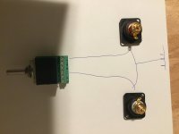
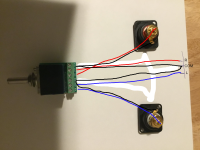
Yes. The two Gnd are not tied together until you plug into the omicron amp board, so take note when testing.
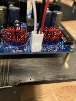
V+ | Gnd | Gnd | V-

V+ | Gnd | Gnd | V-
Yea close enough, carry on. Mine were somewhere around similar values, you'd have to sift through quite a few if you really wanted things to be precisely matched, probably doesn't matter though.
You can plug in the values you used for R5/R6 and R7/R8 to https://www.omnicalculator.com/other/lm317 and see what you get. Then there's resistor tolerances coming into play, and there you go. BOM values net you around 16.85.
You can plug in the values you used for R5/R6 and R7/R8 to https://www.omnicalculator.com/other/lm317 and see what you get. Then there's resistor tolerances coming into play, and there you go. BOM values net you around 16.85.
No need to be super precise. The actual voltage depends on the tolerances of resistors and of the voltage references internal to LM317/337:

But nothing bad happens if the supply voltages are a bit off and/or asymmetric.
But nothing bad happens if the supply voltages are a bit off and/or asymmetric.
I would like to get the wire colors “correct“ on this build. For power should it be V+=red, gnd=white, gnd=white, V-=black, pgood=??
National Electrical Code doesn't apply here, so anyone can choose whatever colors. All wires of the same color would work, as would all the same color except first pin (V+). I use red for positive, white or blue for negative, black for ground, and green for PGOOD, but that's mostly driven by the colors of the wire I have at hand, as well as by the desire to minimize wiring errors when debugging, tweaking, and characterizing the board, which involves many plug-ins and plug-outs.
BTW Molex makes ready-to-use KK254 cable assemblies which might save you from some crimping - with all black wires.
BTW Molex makes ready-to-use KK254 cable assemblies which might save you from some crimping - with all black wires.
That cable would have saved my finger tips!
I do need some help on the volume pot wiring. I have the alps 10k with the breakout pcb. I think it goes like this.
ain = center pin from a rca
aout = right in on amp board
bin = center pin from b rca
bout = left in on amp board
Not sure about the a and b com.
I do need some help on the volume pot wiring. I have the alps 10k with the breakout pcb. I think it goes like this.
ain = center pin from a rca
aout = right in on amp board
bin = center pin from b rca
bout = left in on amp board
Not sure about the a and b com.
a com goes to the right (a) RCA shell and to the common (middle) pin on amp board.
b com goes to the left (b) RCA shell and to the same common (middle) pin on amp board.
b com goes to the left (b) RCA shell and to the same common (middle) pin on amp board.
I thought this old $3 toaster would be a good chassis but it‘s not quite wide enough for the flaps to close. At least I know everything works and sounds great. I’ll clean up the wiring once I get a more permanent chassis. And I have to (get to) buy some decent headphones.
Thanks to @alexcp for this great project and all your help and @bloqhed too for jumping in with some much needed help.
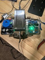
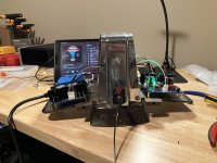
Thanks to @alexcp for this great project and all your help and @bloqhed too for jumping in with some much needed help.


I realize I’m not fully moved in and soldered to everything yet. What would cause a grounding hum, but goes away when the headphone jack ground is also grounded to the chassis? I have no other issues, everything works perfectly and sounds great. I’m using an old 1/4“ adapter I scrounged up, with some cheap earbud.
Not sure which model locking jack you used, but mine have the screw with the red plastic washer like in the picture. I left the washer on as it isolates the ground from the chassis.

That’s the same one I have, I also left the washer on. I was going to see what happened if I took it off but I’m honestly not sure what‘s supposed to happen in either scenario, on or off.
This is how it’s connected from the board to the headphone jack. White to TIP, black to GR, red to RI. I followed alexcp guide he posted above for the volume pot. I’ll try to work up a quick sketch, I must have missed something somewhere. I have a jumper wire from the jack ground to chassis and it’s totally quiet.

- Home
- Amplifiers
- Headphone Systems
- Omicron, a compact headphone amp with -140dB distortion
