I really don’t get members that with no invitation or encouragement, force their “ideas” how would they change someone’s proven design. Simulations are useful, but are by no means any proof that change in design will behave in real circuit as in simulation.
It would be polite to build and measure your circuit with “better performance” 🙄 and post results in the different thread, instead of littering this one.
It would be polite to build and measure your circuit with “better performance” 🙄 and post results in the different thread, instead of littering this one.

Most OPs are open to suggestions, and many designs here has become stellar from other members input. I don't see how Smersh could force anyone to change their designs, even if he wanted to.
I also never knew one had to be invited to comment on a thread. If so I should have been banned years ago.
Cheers!
I also never knew one had to be invited to comment on a thread. If so I should have been banned years ago.
Cheers!
I'm just one of the people who picked up a set of boards during the group buy process, so take my comments accordingly. I'm not a designer but am an appreciative customer.
I for one consider this project to be mature and successful, past the design stage, maybe ready for another group buy at some point if/when there's enough interest. The PCBs have been iterated, tested and proven to sound great. I wouldn't think that @alexcp would want to wade into another iteration of this project (but I cannot speak for him, naturally). I know I wouldn't 🙂
Just speaking for myself but I do agree with @tombo56 - open your own thread, and if there's interest from other members in working with an upgraded design, there you go! +1 on building your own upgraded version in the physical sense.
rockies914 I agree. This project is far past the R&D stage and a dedicated thread should be perfect for the work of SMERSH.
Also, we should respect each others efforts and prevent discouraging members to put in the effort and show their passion. To be specific: keep your rolling eyes on your own side of the internet connection.
Also, we should respect each others efforts and prevent discouraging members to put in the effort and show their passion. To be specific: keep your rolling eyes on your own side of the internet connection.
It would be polite to build and measure your circuit with “better performance” 🙄
Some posts were split off to reassure the fluid continuity of this thread.
Hugo
Moderation team
Hugo
Moderation team
Thank you all for your support!
While I am open to all kinds of ideas, I believe separating the wheat from the chaff is required before declaring a project ready to be built by the public. Before publishing, we played with many ideas, both in simulation and in the actual hardware, and settled for a particular balance of performance, complexity, and cost. Although quite a few people suggested extra complications, I have not seen, or heard, better real-life performance, yet.
Which is not to say it is impossible to make something different or better in some sense. Since Omicron is now past its design stage, I agree that this thread should be focused on supporting and publicizing Omicron builds, while new designs should be considered and discussed separately. Good luck with those!
Last edited:
Hello alexcp, after way to much time I finally had enough to buy to get my last missing parts as well and meet the minimum order for free shipping and could "finish" building my omicron. I followed the assembly guide, but I am stuck here:
I think I have problem, I have a constant very high offset of ~240mv at the output which triggeres (rightly) the LM339 when seated.
I measured R15,R16,R35,R36 and they are all at 42mV, which is a bit lower than it should be.
Do you have any Idea where I can start investigating? (I have an oscilloscope)
- Check the offset voltage at the output of the amplifier. It should be close to zero (typically within +/-50mV) even without the opamps.
I think I have problem, I have a constant very high offset of ~240mv at the output which triggeres (rightly) the LM339 when seated.
I measured R15,R16,R35,R36 and they are all at 42mV, which is a bit lower than it should be.
Do you have any Idea where I can start investigating? (I have an oscilloscope)
Attachments
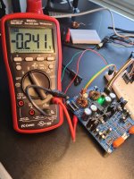
Don't worry and go ahead with the guide. 240mV is a little on the high side from what we've seen, but it is sufficiently "close to zero".
The deviation of the output voltage from zero without the opamp is due to the NPN and PNP transistors not being perfect complements, and is quite normal. With the opamp in place, the feedback loop will take care of this slight un-symmetry of the output stage.
The deviation of the output voltage from zero without the opamp is due to the NPN and PNP transistors not being perfect complements, and is quite normal. With the opamp in place, the feedback loop will take care of this slight un-symmetry of the output stage.
Hi alexcp,
given the excellent performance, I am tempted to try it on my 112dB/W/m horns. What would be the highest (safe) bias for the SMD version?
Kindest regards,
M
given the excellent performance, I am tempted to try it on my 112dB/W/m horns. What would be the highest (safe) bias for the SMD version?
Kindest regards,
M
The SMD board is good for about 25mA quiescent current (each channel) with +/-17V rails. One can reduce the rail voltage to, say, +/-12V (here's how), and raise the current to about 35-40mA.
What is the impedance of your horns? Large voltage swings into low-impedance loads may risk the output transistor's SOA (PZT2222A and PZT2907A are good up to 800mA peak current), as well as starve them of base current, which would sharply increase distortion at signal peaks.
What is the impedance of your horns? Large voltage swings into low-impedance loads may risk the output transistor's SOA (PZT2222A and PZT2907A are good up to 800mA peak current), as well as starve them of base current, which would sharply increase distortion at signal peaks.
Hi alexcp,
first, thank you for the reply.
The impedance is 8 Ohms. I was wondering about it, since I measured about 80 mV RMS for an average 65 dB/m. But, eventually I may have to add a series resistor/L-pad to adjust the level to the low-frequency part of the speaker.
Kindest regards,
M
first, thank you for the reply.
The impedance is 8 Ohms. I was wondering about it, since I measured about 80 mV RMS for an average 65 dB/m. But, eventually I may have to add a series resistor/L-pad to adjust the level to the low-frequency part of the speaker.
Kindest regards,
M
Last edited:
Eight ohms is not a problem as such; for example, we tested Omicron with 8-ohm AKG K3003. It is just that Omicron's output stage is not designed to deliver as much current as a typical loudspeaker may need. By all means, give it a try.
Hi alexcp,
thank you very much again, I will definitely change the voltage to +-12V as you have kindly pointed out.
This brought another idea, would it be possible to further separate the output stage to run from let us say +-5V to further lessen the dissipation thereof?. If it would require a significant re-design, please do not spend any time on it.
Kindest regards,
M
IMHO try it in the stock version first, then decide if you want to modify anything. AKG's 8-ohm IEMs work wonderfully with 25mA bias.
A through-hole board would be a more straightforward way of having more bias and more dissipation. Sadly you don't have that if I remember correctly...
You can try running the whole (SMT) board from +/-5V supplies, use e.g. OPA1642 (which works from +/-2.25V and has been tested to work in the Omicron), and adjust the output stage biasing network accordingly. We have not tested this, but I don't see why it wouldn't work.
Separating supplies for the opamp and the output stage is a fairly standard if more complicated approach. There are a couple of gotchas there; for example, you don't want the transistor's base to swing above its collector. It probably can be made to work, but off the bat, I don't have a ready solution.
Hi alexcp,
thank you for your patience.
Kindest regards,
M
thank you for your patience.
Yes, you remember correctly, the idea did not occur to me then, and since I prefer SMT that was, what I ordered.A through-hole board would be a more straightforward way of having more bias and more dissipation. Sadly you don't have that if I remember correctly...
As I wrote, please do not worry about it.Separating supplies for the opamp and the output stage is a fairly standard if more complicated approach. There are a couple of gotchas there; for example, you don't want the transistor's base to swing above its collector. It probably can be made to work, but off the bat, I don't have a ready solution.
Kindest regards,
M
- Home
- Amplifiers
- Headphone Systems
- Omicron, a compact headphone amp with -140dB distortion