I would like to see Omicron vs discrete headphone amplifier (GainWire MK3, DCG3) who will winner
Wait, you are building it all! Wow. Tell us what you think!Build all and compare.
@ jwchen119
Hi,
Very nice build, congratulations.
Would you please be so kind to add any details on the box (vendor, model, etc.) and (please again) on the potenziometer (valute, model, schematic)?
Thanks in advance, best regards and congratulations again,
Francesco
Hi,
Very nice build, congratulations.
Would you please be so kind to add any details on the box (vendor, model, etc.) and (please again) on the potenziometer (valute, model, schematic)?
Thanks in advance, best regards and congratulations again,
Francesco
I have assembled my smt and power supply boards, but not tested yet. The power supply's common choke's ferrite was little cracked when I got it but now I found out it is fully cracked. Can I test with it or should I find new one before?


Probably hopeless, but if I don't ask there is no chance at all. So if there are a kind soul here, who have a set of boards TH or SMT, that they wont be using or wont be using before the next GB comes around. I would love to build a Omicron right away. Next GB just seams too far away!
Please 🙂
Please 🙂
@fdealexa
Most of the parts are from Taobao(China E-commerce), you will not able to import directly from there but I think you might find most of it on Aliexpress.
The list is only for reference, you can pick them in same spec in most of the time, not necessary to be the same manufacturer.
Hope you get the idea, and having fun building the Omicron.
| Item | Spec | Manufacturer | Note |
| Power switch | 16mm/ 220VAC | Lanboo | The LED is working totally fine at 110VAC but dimmer. |
| Alumiun case | BZ2205 | BRZHiFi | WxHxD = 220 x 52 x 226. |
| Volume knob | 6mm hole | BRZHiFi | Duckbill knob |
| Aluminum flex coupler | 6mm hole | n/a | Suggest to get it from local. Also the hole dimension of coupler is based on the OD of extension bar and the volume pot shaft. And I'm not recommended hard coupler, get flex one will make your life easier. |
| AC power socket | n/a | Schurter | You can pick whatever you want. |
| RCA jack | n/a | REAN | You can pick whatever you want. |
| Toggle switch | SPDT | E-Switch | You can pick whatever you want. |
| Potentiometers | 10K ohms / 2-gang | Alps | You can pick whatever you want. |
| Phone locking jack | NJ3FP6C-BAG | Neutrik | You can pick whatever you want. |
About silk screen of each connectors and led polarity.
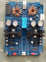
I've soldered THT board and Power board without taking photos.
I want to know wiring between power board and dc protection board .. as you know the dc protection board has 5 pin power connector and the power board has 4 pin aux connector.
...and want to know wiring of 'ground connect' pin of dc protection board.
Just sent you some pictures.
The power supply board, Omicron board and the protection board all have the same pinout of the 5-pin power connector: +V, GND, GND, -V, /PWR_GOOD. The second output connector on the power supply board doesn'e have the /PWR_GOOD pin, but the other four pins are in the same order as on the other connector +V, GND, GND, -V.
If using the power supply board with Omicron, just connect the 5-pin connectors on each board together, pin to pin.
If using Omicron's power supply and protection board with another headamp, connect connect the 5-pin connectors on power supply board to the 5-pin connector on the protection board, and use the 4-pin output on the power supply to power your other headamp. The GROUND CONNECT jumper on the protection board should be left open. Short it only in the unlikely scenario when the headamp and the protection use power supplies with separate grounds.
Hi Alexcp, thanks for sharing this great design.Simplified schematic (links to the full schematic are below):
I'm quite new to the analog world. I have some newbie questions about the feedback networks.
The 2nd order HP filter on the second opamp gives a 180-degree phase shift. Will it cause the opamp to oscillate? I understand the final schematics use a one-pole HP in parallel, but I wonder if the decision to use this 2nd order HP is really needed to get faster decay?
To my understanding, this design pushes the gain in the lower frequency band ( < ~230k) to the maximum, thus achieving a really low distortion. The magic is to use global feedback to limit the total gain, but the second stage is more like a subtractor of HF. Is it right?
If my read is right, can I use this design as an active LP filter by adjusting the gain to 1?
Thanks, really love your work
okdc offet - 3~4mV
10x what it should beR15, R16 - 610~620mV
a bit low but okR35, R36 - 40mV
way too highC13, C14, Q1, Q2 - about 100 ℃
a bit high but okC33, C34, Q21, Q22 - about 50 ℃
Can you please check the voltage across each of R11 R12 R13 R14 and R31 R32 R33 R34?
Thank you for your kind words. I am sorry to say that no, you don't seem to understand how it works. The explanation would be lengthy and out of place in a forum post. Have a look at my blog instead - there, I am trying to cover some feedback theory basics as it applies to audio amplifiers.Is it right?
- Home
- Amplifiers
- Headphone Systems
- Omicron, a compact headphone amp with -140dB distortion