that's exact reason for existence of Babelfish M25
in last iteration even fully DC coupled all the way, from input to output
in last iteration even fully DC coupled all the way, from input to output

last iteration is pretty much same as SissySIT (42), regarding everything preceding output source follower
anyhow, no reason that biasing mechanism, when properly done, is influencing bandwidth in any practical way
anyhow, no reason that biasing mechanism, when properly done, is influencing bandwidth in any practical way
I made a rookie mistake and swapped Q1 and Q2 (044 and 9240) on one channel. I only noticed when I saw the 0R47 resistors R13 and R14 in that channel glow red and quickly switched off the amp. The fets were mounted on their big modushop heatsinks and the amp was only on for perhaps 10 seconds.
I removed the resistors and mosfets and used a dmm to test the on and off charateristics of the mosfets (using some utube videos as a guide). They seemed to be ok, so I put them in their correct position and put fresh 0R47 resistors in.
I tested the amp today. No smoke 😎
I was able to get the offset nicely to 0mV and let it cook for a bit. I then hooked it up to a source and my test speakers and thought I only heard one channel. I swapped source and speaker cables to make sure the fault was in the amp, checked continuity between the input rca and the board which was fine. After disconnecting the speaker of the working channel I noticed the 2nd channel was actually playing, only at much lower volume and sounded muffled (no highs).
What could I have fried? Is it the mosfets (the simple test showed they were ok but perhaps they don't like the treatment received)? I hope not because I used my last 9240.
Or could it be the 4N35?
The other smaller resistors (Dale RN55) all looked fine.
Any suggestions would be appreciated.
Attachments

change mosfets
triple-recheck source resistors, and - best - change them too
rest (opto) is pretty well protected
triple-recheck source resistors, and - best - change them too
rest (opto) is pretty well protected
Thanks ZM. Source resistors were already replaced.
I have plenty of 044s, but no 9240s left. I can't get them locally so I am afraid it will have to wait until I place my next order at mouser.
I have plenty of 044s, but no 9240s left. I can't get them locally so I am afraid it will have to wait until I place my next order at mouser.
you can use 9140 a well, just take care to have same types in both channels
anyhow, schooling, you paid it cheap actually
from now on, if in situation that you can't see type of part when mounted, use old trick (from those who paid same school***) - always paint N channel parts pins with red sharpie
or put piece of paper tape on edge of part or whatever......
*** had one channel of Babelfish M25 assembled with N channels, second with P channels
Pass DIY Addict
Joined 2000
Paid Member
We've all been there. I swapped the push for the pull output transistors in my very first build - my a40 - about 20 years ago. It smoked one channel's worth of output devices, a handful of resistors, and one or two of the small signal transistors that drove the outputs. It was so disappointing to have worked for so long on my first amp only to see the magic smoke escape with the first power up.
Having learned my lesson, I now use a dim bulb tester and a variac for first power up. I still check things three or four times before I power up for the first time... I'm sure Zen will label me a sissy for my precautions, but I'm good with that 😎.
Having learned my lesson, I now use a dim bulb tester and a variac for first power up. I still check things three or four times before I power up for the first time... I'm sure Zen will label me a sissy for my precautions, but I'm good with that 😎.
Thanks for the encouragement. It was just plain stupidity. I have a variac in the cupboard but being in a hurry and knowing the psu was fine I just went ahead and switched it on. Haha, let's try not to make that mistake again!
I'm sure Zen will label me a sissy
ZM is having Variac on the bench, right under the hand reach
ZM Omnichicken

What is the definition/difference of signal transformer and autoformer with primary and secondary connected.? I saw ZM post saying latter being 5+1v gain or something. So am I just getting a bit more gain with autoformer setup or is there more to it?
I don't have Edcor but do have some Chinesuem shielded 600:20k I'd like to try on a preliminary build and have the option to wire however I like!
I don't have Edcor but do have some Chinesuem shielded 600:20k I'd like to try on a preliminary build and have the option to wire however I like!
After mistakingly swapping the NPN and PNP mosfets, I ordered replacement 9240s (I had spare 044s).
My new 9240s came in so I dismantled the amplifier and replaced both mosfets in the affacted left channel. After putting it back together again the problem remains the same. The unaffected channel sounds great but the affected channel is much lower gain (I have to disconnect the right speaker to hear it properly because it is so much softer). Also the sound from the affected channel is not as clear and sounds a bit distorted.
[Yes, I have swapped input cables to make sure it was not the source and also swapped speaker cables to make sure the problem really was caused by the left channel of the amp. It uses a single psu for both channels, and the other channel works fine, so it is not caused by the psu. Also, before taking the F5 board out and replacing them by the M2 boards, the F5 had worked fine, so I know the psu was working.]
Besides replacing the mosfets, I previously checked all the soldering, resistor values, diode directions, etc but found nothing wrong.
After putting it back together again today (same problem), I have taken the amp apart again and have the affected left channel pcb and heatsink on my workbench. I will check all resistor values again later this week, as well as diode directions and anything else I can think of.
A few questions.
1. I remember during testing a week or so ago, both heatsink were getting warm, so I assume the bias circuitry is working. Nevertheless, would a defective 4N35 or LM385 cause a similar result?
2. Assuming the mosfets are working fine (judging by the heatsinks warming up), can this be caused by a defective Edcor?
Thanks
considering how many parts you have in output stage, just replace them all
is it damaged gate resistor or damaged/leaky diode, or protecting LM, or opto, or damaged trace somewhere
one thing you could do while channel was assembled - you could actually measure Iq of mosfets, same as output offset....
is it damaged gate resistor or damaged/leaky diode, or protecting LM, or opto, or damaged trace somewhere
one thing you could do while channel was assembled - you could actually measure Iq of mosfets, same as output offset....
I just need to screw the pcb and transistors back to the heatsink to test iq. I'll use my bench psu to check.
Assuming the output stage is fine, how can I test the input stage?
The strange thing offset was easy to get to 0mV, and it does play music, just very softly and not as clear as the other channel.
Possible problem with the edcor?
Assuming the output stage is fine, how can I test the input stage?
The strange thing offset was easy to get to 0mV, and it does play music, just very softly and not as clear as the other channel.
Possible problem with the edcor?
it's simple as taking any signal source and feeding input of an amp, then measuring points of interest
it can be output of laptop with simplest prog playing 1K sine
that signal any semi-decent DMM can measure
so, measure input signal - say 200mV (set by you )
measure what you have on buffer output node
measure what you have on Edcor output
in all steps,. black probe to GND, red to mentioned node, DMM set to Vac, no load at output of amp needed
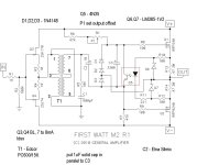
if you need specific info about nodes, post exact schm or link to
it can be output of laptop with simplest prog playing 1K sine
that signal any semi-decent DMM can measure
so, measure input signal - say 200mV (set by you )
measure what you have on buffer output node
measure what you have on Edcor output
in all steps,. black probe to GND, red to mentioned node, DMM set to Vac, no load at output of amp needed
if you need specific info about nodes, post exact schm or link to

- Home
- Amplifiers
- Pass Labs
- Official M2 schematic