OK, I see I have explained badly. My apologies. I have already built an M2, using a transformer similar to the one you describe. (I like the amp, BTW.) That is not what I am talking about doing here.Analyze the M2 circuit schematic (found in post #1 of this thread) again. You'll discover that "the power demand of the M2 amp" is far greater than 28 watts per channel. Since M2 operates in class A, the power it draws from the power supply is a LOT more than the power it delivers to the loudspeaker load.
You can do a "sanity check" on your calculations by visiting the First Watt website and downloading the owner's manual for the M2. In the specifications table you'll find a line-item that tells you the power an M2 draws from the AC mains. Hint: it's a lot more than 28 watts per channel.
*you calculated 28 watts * 2.5X safety factor = 70 watts for the power transformer. But I suggest that 28 watts is far too low.
If this helps: I used a 400 volt-ampere toroidal transformer to build my (stereo) M2x. That transformer had 2 x 18VAC secondaries at 11 amperes each. I actually planned to use a 300 VA transformer, 2 x 18VAC at 8.3 amperes each . . . . . but those were out of stock on the day I bought. So I paid a little more money and got the 400VA because it was available immediately.
I have two transformers. Each is 160VA, 25V - 0 - 25V center-tapped secondaries. So dividing by the usual 2.5 safety factor, I have something like 60 - 70 watts per channel to play with.
I am considering trying a mini-M2 using these transformers. (With some sort of different front end.) A PSU with such a transformer is going to give +/- 32V or so after rectifying and smoothing. Maybe a little more, but probably not less. This is far more rail voltage than I need.
If I bias at around 800mA then I'll continuously burn 51W on the heatsink. But this should be within the capability of the PSU.
At 800mA bias I have should have around 10W output power in class A. I calculate that as follows. Bias of 800mA means the amp leaves class A when peak current on the output is 1.6A (push-pull, so twice the bias, right?). Into an 8R load that is 8 x (1.6)^2 /2 = 10.24 W. (Dividing by 2 for RMS rather than peak current.)
Does that sound right? (I'm not an engineer, in case it wasn't already obvious.)
My question: If the last calculation is correct then my guess is that I should have more power available in class AB, but how can you calculate/estimate it?
Thanks
Nigel
Hi ZM,first thing first
in which arrangement you want to have FE made, and is that feasible with elevated rails?
depending of set Iq, with 25Vac secondaries, you'll end with rails in range of 32 to 35Vdc
so, think in those relations, deduce what's clever to do regarding FE and later think about OS
I realise the front end is going to have to be thought out. And yes, I understand the higher rails may be a problem for that.
The starting point was these nice transformers and what to do with them. (Which as you say is probably the wrong way round to do things.) A smaller class A amp than the Pass amps I've made seemed a possibility, so I started thinking about what class A output would be, then realised I didn't know how to figure out what class AB output might be. Hence the question.
Nigel
You’re not going to have more power because AB, youll have more power because the total voltage swing will be higher, due to increased rail voltage.
The real question is can the circuit take the additional voltage with no ill effects?
The real question is can the circuit take the additional voltage with no ill effects?
Hi 6L6,
Yes, I understand the main point is that the rail voltage is higher, not that it's AB. But it certainly won't be class A beyond relatively low power if bias is only 800mA, right? Anyway there are front ends that can handle such rails. Like BA3 FE, for instance, I think. I guess I'd better think about the whole plan and repost later.
I'd still like to know if 10W in class A sounds right, for 800mA bias? (I don't think biasing higher is reasonable with the higher rails and smaller trafos.)
Best
Nigel
Regardless of the specific amp...I'd still like to know if 10W in class A sounds right, for 800mA bias?
~11-12W into 8R => ~10Vrms ~1A6rms
Close enough.
2 x 160VA => More VAs than 1 x 300VA transformer used in a production M2 if you don't want to bother with figures etc. 🙂
That's how I might think about it... but ... my thoughts are often wrong.
Edited to add - but... when YOU are thinking about it... the total dissipation is also a direct function of the rail voltages... so, until you settle on that... you won't know if you're good to go or not.
Last edited:
This seems to have gone unmentioned in the most recent discussion:
The M2 output stage has a fixed bias current of about 1.3A. It is not adjustable. Only the DC offset is adjustable.
The M2 output stage has a fixed bias current of about 1.3A. It is not adjustable. Only the DC offset is adjustable.

Maybe this will help you, Section 5.1 in particular :
https://sound-au.com/power-supplies.htm
Note that to get full use of the higher rail voltage, the front end must be capable of the high voltage output as well.
The OPA551, for example, is rated at +/-30V rails absolute maximum.
The corresponding maximum output is then +/-27V.
A unity gain buffer OPS is likely to lose another volt or so.
So irrespective of bias and amplifier class, you are not likely to get more power than that.
Hope this helps,
Patrick
Why a heavy class A bias in a push-pull design?? Just to reduce the distortions (in a no-feedback design)??
AB power is relate to voltage psu ,live the A is relate to 2xbias currentMy question: If the last calculation is correct then my guess is that I should have more power available in class AB, but how can you calculate/estimate it?
https://www.diyaudio.com/community/threads/rail-voltage-chart-for-amps.177382/
Note that to get full use of the higher rail voltage, the front end must be capable of the high voltage output as well.
The OPA551, for example, is rated at +/-30V rails absolute maximum.
The corresponding maximum output is then +/-27V.
A unity gain buffer OPS is likely to lose another volt or so.
So irrespective of bias and amplifier class, you are not likely to get more power than that.
Front ends that include a step-up transformer, operate on different principles. For example, the First Watt M2 front end includes an Edcor PC600-15K transformer whose turns ratio is 1:5 (see post #1 of this thread). To get an output swing from -40V (trough) to +40V (peak) at M2's Edcor secondary, you need to drive its primary with a swing from -8V to +8V.
A large number of discrete circuits, and integrated circuits, are able to swing 16 volts peak to peak -- so there are plenty of options available to builders who decide to include a transformer in their front end. You don't need 60 volt opamp chips (or 60 volt discrete circuits) when there's a step up transformer; M2x Tucson and M2x Cedarburg exhibit a couple of ways to safely use plain ordinary +/- 15V circuits (IC chips) which are fed from much higher voltage supplies, and those are only the tip of the iceberg.
I realise the front end is going to have to be thought out.
decide your FE arrangement, so we can detail that first
OS is doable with your xformers, no doubt
though - probably too much of hassle, for my liking
Thank you all for the help. Lots to think about. ZM may be right, though, and perhaps it might be better to find a different use for these transformers. I'll give it some thought.
Well, it's kinda odd, not that I posted many interesting things on, the old forum but I don't even remember creating this account, though I can see why I did.
I remember talking on the Nakamichi PA-7 on the old forum on another account but not this one and I had to reread my own messages.
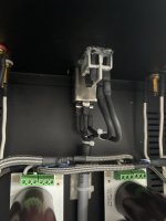
Anyway, I am in love with the M2 amp, I actually now own the M2 Tea-Bag pcb made by uchu007 years ago and I feel like I am kinda late to the party, I'll enjoy reading everything about this amp and all the topic page. I may fancy myself a M2X Mountain View one day since I quite like this amp but I feel like I'll try sooner or later to add some mu metal to shield it as everybody seems to have done it, funny thing is that maybe the room is quite cold but I don't feel it going that hot unless I crank more the volume pot (or it's taking its sweet swiss time to heat up).
Here are some pictures of it.


Maybe I should check also if screws didn't come lose over time.
I remember talking on the Nakamichi PA-7 on the old forum on another account but not this one and I had to reread my own messages.
Anyway, I am in love with the M2 amp, I actually now own the M2 Tea-Bag pcb made by uchu007 years ago and I feel like I am kinda late to the party, I'll enjoy reading everything about this amp and all the topic page. I may fancy myself a M2X Mountain View one day since I quite like this amp but I feel like I'll try sooner or later to add some mu metal to shield it as everybody seems to have done it, funny thing is that maybe the room is quite cold but I don't feel it going that hot unless I crank more the volume pot (or it's taking its sweet swiss time to heat up).
Here are some pictures of it.
Maybe I should check also if screws didn't come lose over time.
Attachments
I wonder if anyone has ever tried the M2 with Cinemag transformer. Eg CMOQ-4LPC? Just bc I have a pair lying around 😂
Pass DIY Addict
Joined 2000
Paid Member
Attachments

Oh yeah, put it on, and enjoy it ! I think to have or make a preamp with no nfb to go with it. In the meantime, I am gonna read more the post about M2, I stopped where it was mentioning 3rd harmonics from the amp. I am used to very dynamic amps with precise and clear sound such as M-7050, M-L10. I gotta say this one doesn't hold back to them but it adds the last bits of realism I lacked for the full immersion. Or maybe it's because of the novelty, gotta listen more to it when possible.
Yeah, the Tea-Bag are clean boards, I wonder what the difference with a Mountain View would be. In any case, the clean build must help and big passive cooling, it's not as hot as I thought it would be, it's hot yes, but only if I hold my hands on the top of radiator. If I just touch the chassis or the side of radiator, it's way less hot.
It's really interesting. I'll see more tomorrow what some Tara labs free cd can bring and if they bring something to it but I do love this amp. It kinda makes me curious about the AX-25 as well.
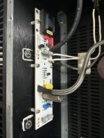
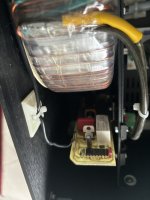
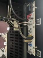
However, in this build, there are two circuits that the builder added and for which I have no idea what they do, I'll post more pics tomorrow while tightening every screws.
Yeah, the Tea-Bag are clean boards, I wonder what the difference with a Mountain View would be. In any case, the clean build must help and big passive cooling, it's not as hot as I thought it would be, it's hot yes, but only if I hold my hands on the top of radiator. If I just touch the chassis or the side of radiator, it's way less hot.
It's really interesting. I'll see more tomorrow what some Tara labs free cd can bring and if they bring something to it but I do love this amp. It kinda makes me curious about the AX-25 as well.
However, in this build, there are two circuits that the builder added and for which I have no idea what they do, I'll post more pics tomorrow while tightening every screws.
As a happy builder & user of M2 I have a memory of seeing a schematic for an M2 that had been modified to accept a single ended supply. I'd like to revisit it for the purposes of simplifying a small desktop mini system but my google foo is failing me. Does this ring a bell for anyone?
Can't help with the schematic you're after, but why not build an ACA? It uses a simple DC supply and to my ears sounds better with the premium parts suggested by @TungstenAudio, especially for desktop use.
I have an original M2 (teabag) in a main system, but now prefer the Premium ACA for pure music enjoyment.
I have an original M2 (teabag) in a main system, but now prefer the Premium ACA for pure music enjoyment.
- Home
- Amplifiers
- Pass Labs
- Official M2 schematic