The trouble I experienced with the M2 DC offset that was drifting was due to a blown IRFP9240. I am convinced the supplied Harris Mosfets are fake - or at least the P channels. The surface texture of the package looks suspicious.
The last bit of trouble I am encountering is a slight bit of hum - but it is not magnetically induced. I have moved the channel with heatsink away from the mains transformer and the hum level remains the same. It must be some ground loop issue - yet I have connected everything as per textbook.
I had two copper ground connector planes made for the capacitor banks. Came out well.
Cut the copper planes as per the above. Your common returns should be:
1. connection to chassis
2. speaker negative return
3. connection to AMP PCBs ground
Have a look at No 4 above.... the current sharing between the 2 resistors will be impacted by a thin wire link you used for one of them. These links need to be of the same diameter and length for both resistors.
I see that you used an E-core transformer. It is shielded quite well against magnetic radiation and RF radiation, which is good. However, I do not believe that's enough for that beast of a transformer. The magnetic field force radiating from that thing will hit the capacitors right on. Options??? Well, you ain't gonna like it... try a toroidal transformer, well shielded (in your case that's a must, because everything is so tight!!!).
I would definitely rotate the amp PCB modules 180 degrees along the vertical axes - your DC wiring is waaaaay too long. The power supply needs to provide full current capabilities (delivery) at the full audio frequency spectrum. It needs to be of a constant, low-impedance type. At the moment, that will work in your case for the mid to mid-high frequency range only. So, much shorter and thicker wires are required for the low-frequency range, and fast supply capabilities are required for the high-frequency range. You can achieve the speed required at high frequencies by bypassing those electrolytic capacitors with film capacitors. Experiment a bit (start with around 10uF polypropylene film caps). The end value will greatly depend on the wiring length and thickness between the power supply caps and the AMP PCB. FW amplifiers and clones do not have the local power supply rails' decoupling on the boards... so you need to do the best you can "externally".
Sorry...yes you are right. I use the teebag PCB and no official PCB ist existing for M2.Although there is an "Official M2 Schematic" (post #1 in this thread), there is no "official M2 PCB". There's a tea-bag M2 PCB, and there's a diyAudio Store M2x PCB. and there's a Prasi M2 PCB, but none of these are "official".
Yes i always use the scope to look at the amp.How did you measure the above?? Did you use an oscilloscope to look at the amplified sinewave? This measurement should be done with nothing connected to the output. The output sinewave will start to clip earlier due to slightly lower than desired supply rails. You'll be able to get an extra volt of 2 if your rails are around 24-25V loaded. The 2 X 20V AC secondary's transformer will get you there. This will allow the full gain ability of Edcores to reach the amp output, without being clipped by the low supply rails.
First Sound then Power...😉
How did you measure the above?? Did you use an oscilloscope to look at the amplified sinewave? This measurement should be done with nothing connected to the output. The output sinewave will start to clip earlier due to slightly lower than desired supply rails. You'll be able to get an extra volt of 2 if your rails are around 24-25V loaded. The 2 X 20V AC secondary's transformer will get you there. This will allow the full gain ability of Edcores to reach the amp output, without being clipped by the low supply rails.
Attachments
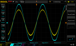
load are 4R each channel driven, rail is satable about 22,7V each rail.
2x300VA 18V transformer with secondary parallel together - company Sedlbauer
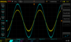
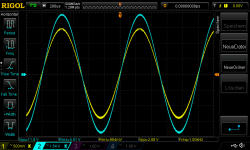
as you can see i try to find out, if i have early clipping of the low transconductance of the PMOS...but it comes late. so its ok
2x300VA 18V transformer with secondary parallel together - company Sedlbauer
as you can see i try to find out, if i have early clipping of the low transconductance of the PMOS...but it comes late. so its ok

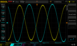
oh ...the first pic is the fg of 1,4Vrms input with 16,6Vpp out at 1khz...so at 104khz i get about 11,7Vpp -3dB
now the 1khz power measurement with 1Vrms in --> 4WATT
now the 1khz power measurement with 1Vrms in --> 4WATT
Attachments
Last edited:
Hi
do you have a proposal for PCHMOSFET with higher transconductance of 20-36 S that is stable and with good recommendations?
active and available (...time is strange)🙄
😆
e.g.IXTH52P10P 20S....to less together with the FQA Nchannel ?
do you have a proposal for PCHMOSFET with higher transconductance of 20-36 S that is stable and with good recommendations?
active and available (...time is strange)🙄
😆
e.g.IXTH52P10P 20S....to less together with the FQA Nchannel ?
Last edited:
Thank you for your reply. As much as I want to, I cannot really agree with any of it. I cannot use a toroid as the chassis is already made, I cannot rotate the PCB modules, as the chassis is already made. I have moved the PCB modules with heatsinks away from the PSU with zero change in the very slight hum. Also, in regards with the capacitors near the transformer - this is a common practice in many commercial amplifiers to I don't see it being a problem. The same goes with the ground connections. I changed it up and it did not make a difference.View attachment 1129141
Cut the copper planes as per the above. Your common returns should be:
1. connection to chassis
2. speaker negative return
3. connection to AMP PCBs ground
Have a look at No 4 above.... the current sharing between the 2 resistors will be impacted by a thin wire link you used for one of them. These links need to be of the same diameter and length for both resistors.
I see that you used an E-core transformer. It is shielded quite well against magnetic radiation and RF radiation, which is good. However, I do not believe that's enough for that beast of a transformer. The magnetic field force radiating from that thing will hit the capacitors right on. Options??? Well, you ain't gonna like it... try a toroidal transformer, well shielded (in your case that's a must, because everything is so tight!!!).
I would definitely rotate the amp PCB modules 180 degrees along the vertical axes - your DC wiring is waaaaay too long. The power supply needs to provide full current capabilities (delivery) at the full audio frequency spectrum. It needs to be of a constant, low-impedance type. At the moment, that will work in your case for the mid to mid-high frequency range only. So, much shorter and thicker wires are required for the low-frequency range, and fast supply capabilities are required for the high-frequency range. You can achieve the speed required at high frequencies by bypassing those electrolytic capacitors with film capacitors. Experiment a bit (start with around 10uF polypropylene film caps). The end value will greatly depend on the wiring length and thickness between the power supply caps and the AMP PCB. FW amplifiers and clones do not have the local power supply rails' decoupling on the boards... so you need to do the best you can "externally".
As for those "Thin wires on the resistors" that you mention - I can assure you they are thick enough. And as for the DC lines - no trouble in them being 8 inches long. I have seen First Watt builds with the PSU connected via an Umbilical Cable without ill effect.
I want to attribute the hum to the amplifiers possible low PSRR. It is barely audible.
The fact that you disagree with what I say because you did it wrong in the first place doesn't mean that I am wrong.
You do whatever you want to do...
You do whatever you want to do...
Thanks for your honesty.The fact that you disagree with what I say because you did it wrong in the first place doesn't mean that I am wrong.
You do whatever you want to do...
... I have seen First Watt builds with the PSU connected via an Umbilical Cable without ill effect.
I want to attribute the hum to the amplifiers possible low PSRR. It is barely audible.
You may or may not be referring to my M2 build with 2x SMPS in an external enclosure, connected by umbilical cord. The reason for SMPS is that I think all amps with autoformers are prone to picking up hum, etc. from other transformers in close proximity. I might as well have put the SMPS' inside the enclosure, but I prefer them in a cooler environment. I've once read the expression "as quiet as the deep sea". Well, that describes my M2.
I fully agree on the risk of magnetic coupling to the audio transformer but I have tested my build and moved the channels away from the mains transformer - that did not change the slight level of hum at all.You may or may not be referring to my M2 build with 2x SMPS in an external enclosure, connected by umbilical cord. The reason for SMPS is that I think all amps with autoformers are prone to picking up hum, etc. from other transformers in close proximity. I might as well have put the SMPS' inside the enclosure, but I prefer them in a cooler environment. I've once read the expression "as quiet as the deep sea". Well, that describes my M2.
Can you fill me in on how you accomplished this? The splitting of the rails using a DC source I mean. I'm assuming these are standard DC out Meanwells or are they a specialty item?ERRATUM
In my previous post, the first sentence should read:
The two Meanwell SMPS's work very well and were much cheaper than a toroid transformer would have cost.
.
.
This diagrammatic sketch shows the connection of the two SMPS.

The Meanwell's are stock standard LRS models. There was no need to even lift the grounds as some suggest.
Also have a look at the diagram in this post.
The Meanwell's are stock standard LRS models. There was no need to even lift the grounds as some suggest.
Also have a look at the diagram in this post.
Last edited:
This seems too good to be true 🙂 I wonder if this will work with a pair of DC-DC regulators like so:connection of the two SMPS
This diagrammatic sketch shows the connection of the two SMPS.
View attachment 1134904
The Meanwell's are stock standard LRS models. There was no need to even lift the grounds as some suggest.
Also have a look at the diagram in this post.
Some MeanWells have DC coupled mains ground pin to their negative DC out terminal; some don't. This should be checked first.
Absolutely. I said it wasn't necessary with the LRS Meanwells I used, but thanks for pointing that out. The diagram I posted also has a warning to that effect.
This seems too good to be true 🙂 I wonder if this will work with a pair of DC-DC regulators like so:
No idea, maybe someone with more knowledge can advise here. Or you could try it, but measure voltages first.
This absolutley works, I’ve powered a F5 with a pair of LRS-150-24. As safety earth is not connected to V- in the SMPS, you can connect the outputs in series and call the middle point GND. (As we do in normal bipolar PSU)
Would it work with the big AC-DC brick and the small DC-DC bricks? Probably.
Would it work with the big AC-DC brick and the small DC-DC bricks? Probably.
- Home
- Amplifiers
- Pass Labs
- Official M2 schematic