I hear ya! The hottest I have ever been in my life was visiting family in Texas, we went to a Rangers baseball game and it was 99°F at night!!! Not comfortable for a northeastern guy 😳
This is what I was looking for.If you mean matched, no.
Wanted to know if the output transistors needed to be matched.
🙂
Good evening, friends
I completed an M2 build this weekend but apart from the one Edcor transformer having broken wires the left channel suffers from DC offset drifting. It drifts as much as 200mV as a slow tempo - let say taking about 1 minute to do a full swing and bobbing back. Could this be the Opto-coupler? I have replaced the bias diode string. The DC offset pot does adjust the offset as well as the right channel. I have compared the voltage measurements between the channels on all points and everything checks out.
I have also scoured the thread to see if someone experienced the same issue but could only see the issue with the transformer wires that's broken.
@deltavektor
Just to clarify...you're talking about two seperate issues? (1) A broken wire on one of the Edcor's windings (which you repaired?) and (2) DC offset is slowly drifting in one channel. Is that correct?
I would think the transformer should go back to the factory for replacement.
Just to clarify...you're talking about two seperate issues? (1) A broken wire on one of the Edcor's windings (which you repaired?) and (2) DC offset is slowly drifting in one channel. Is that correct?
I would think the transformer should go back to the factory for replacement.
Both these problems are on the one channel. The transformer is now fixed but the DC offset is doing a very slow see-saw drift. Too slow to be called a subsonic oscillation but I guess the term fits.@deltavektor
Just to clarify...you're talking about two seperate issues? (1) A broken wire on one of the Edcor's windings (which you repaired?) and (2) DC offset is slowly drifting in one channel. Is that correct?
I would think the transformer should go back to the factory for replacement.
100 ohms Dale resistors as per Mr Pass' designwhat value of gate stoppers?
So you ran the one channel (left) with the defective Edcor at one point? Meaning there was basically no transformer in the circuit a that point?
Well I was unaware that the transformer was faulty and only spotted the broken wires after I investigated.So you run the one channel (left) with the defective Edcor at one point? Meaning there was basically no transformer in the circuit a that point?
What am I in for? The output FETs bias up perfectly. And the input FET pair produces clean waveforms.
So my question is, what damage could be caused (if any) by operating an M2 with no transformer in the circuit? Did you visually notice any odd behavior prior to repairing the Edcor? Smoke? Excessive heat? Reading on meter?
no damage
I asked for gate resistors, there is a chance that you have slightly misbehaving mosfet , on the verge of collecting HF in gate, so slightly increasing gate resistor could help
only one way to check that
btw. bad opto should result in wandering Iq, not output offset
so, if you trust that everything is decently soldered, try gate resistors first
No strange behaviour at all. Just an incomplete audio path from the transformer to C2.So my question is, what damage could be caused (if any) by operating an M2 with no transformer in the circuit? Did you visually notice any odd behavior prior to repairing the Edcor? Smoke? Excessive heat? Reading on meter?
I will certainly have a try at the gate stoppers and report back.no damage
I asked for gate resistors, there is a chance that you have slightly misbehaving mosfet , on the verge of collecting HF in gate, so slightly increasing gate resistor could help
only one way to check that
btw. bad opto should result in wandering Iq, not output offset
so, if you trust that everything is decently soldered, try gate resistors first
After what felt like YEARS of trial and error, I finally got my old sound card to talk to the DiAna s/w thru ASIO4ALL. So here's the residual distortion as seen in DiAna at 1W into 8ohms. Finally a way to confirm H2 (and H3) phase in vivo... yep it's negative.... coolIn my M2 clone, I added a 1R3 ohm resisitors in parallel with the original 0R47 source resistors to lower them to 0R345.
I simply removed them from the R2 positions and zeroed the output offset to try favoring the P-ch. It raised H2 to about the same level as H3 as seen in the measured spectrum.
I like the sound, more relaxed and spacious was my impression. I'll leave it like this for a while.
I need to get a twin-T notch filter built to look at the residual distortion in real time.
Cinco
Attachments


Last edited:

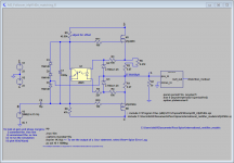
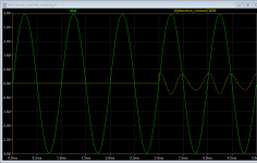
you can alter it - changing type of mosfet in OS
different xconductance, different THD Spectra
see what you get with IRFP150 in place of IRFP240
different xconductance, different THD Spectra
see what you get with IRFP150 in place of IRFP240
not what I was saying
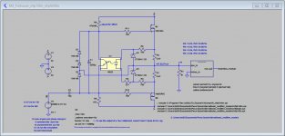
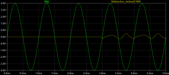
leave same original source resistors, just add another IRFP240 up, ( so having pair of 240 up, just one 9240 down)
that's cheating LTSpice , in vivo IRFP150 is practically pair of IRFP240 in one case
leave same original source resistors, just add another IRFP240 up, ( so having pair of 240 up, just one 9240 down)
that's cheating LTSpice , in vivo IRFP150 is practically pair of IRFP240 in one case
Yes Diana is a wonderful woman! Thanks to the creator!After what felt like YEARS of trial and error, I finally got my old sound card to talk to the DiAna s/w thru ASIO4ALL. So here's the residual distortion as seen in DiAna at 1W into 8ohms. Finally a way to confirm H2 (and H3) phase in vivo... yep it's negative.... cool
- Home
- Amplifiers
- Pass Labs
- Official M2 schematic