Thanks Tungsten. I will certainly try it. 👌
If I may show my lack of electronics knowledge... would you be so kind as to explain exactly where and how to connect the capacitance in reference to +V and -V, please. I suppose I can check how it's done on the universal PSU board.
If I may show my lack of electronics knowledge... would you be so kind as to explain exactly where and how to connect the capacitance in reference to +V and -V, please. I suppose I can check how it's done on the universal PSU board.
Last edited:
Right, I have had single rail PSU in my head lately.
Separate bulk capacitor banks for +V to GND and GND to –V. For each channel of course. The point where the speaker return lead is connected is also important. Looks like you already have excellent low hum, so consider a way of making the GND connection of the extra bulk capacitance to the same point where you have your speaker return.
Separate bulk capacitor banks for +V to GND and GND to –V. For each channel of course. The point where the speaker return lead is connected is also important. Looks like you already have excellent low hum, so consider a way of making the GND connection of the extra bulk capacitance to the same point where you have your speaker return.

I'm thinking about trying a mod to get negative phase 2nd harmonic out of my M2 clone.
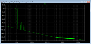
Here's the actual spectrum without the mod. The 2nd harmonic is nulled in my amp. This is with the source resistors equal at 0R345.

Simulation of the current circuit values shows a little more positive H2. Spice models don't match the real-life Toshibas in my amp I guess.


Ok so here is the mod I'm thinking about trying, de-generate the N-ch FET a little more by changing it's source resistor value to 0R47 and leaving the P-ch source resistor at 0R345.

So here are the results, in simulation anyway...
A little more 2nd and it's negative now!


It looks like the bias circuit will maintain a stable imbalance like all of Zen Mod's iterations of the M2 with mismatched OS devices.
I think I will try it.
Cinco
Here's the actual spectrum without the mod. The 2nd harmonic is nulled in my amp. This is with the source resistors equal at 0R345.
Simulation of the current circuit values shows a little more positive H2. Spice models don't match the real-life Toshibas in my amp I guess.
Ok so here is the mod I'm thinking about trying, de-generate the N-ch FET a little more by changing it's source resistor value to 0R47 and leaving the P-ch source resistor at 0R345.
So here are the results, in simulation anyway...
A little more 2nd and it's negative now!
It looks like the bias circuit will maintain a stable imbalance like all of Zen Mod's iterations of the M2 with mismatched OS devices.
I think I will try it.
Cinco
Attachments
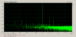
In my M2 clone, I added a 1R3 ohm resisitors in parallel with the original 0R47 source resistors to lower them to 0R345.
I simply removed them from the R2 positions and zeroed the output offset to try favoring the P-ch. It raised H2 to about the same level as H3 as seen in the measured spectrum.
I like the sound, more relaxed and spacious was my impression. I'll leave it like this for a while.
I need to get a twin-T notch filter built to look at the residual distortion in real time.
Cinco
Attachments

The M2 responds well to twiddling.. 
That is why the M2x, with its many different front end buffers, is popular. One of my favorite front ends is still the Austin, a diamond buffer topology that seems to add a bit of 3D presence. Probably just a wee dose of H2, but it sounds very nice.
That is why the M2x, with its many different front end buffers, is popular. One of my favorite front ends is still the Austin, a diamond buffer topology that seems to add a bit of 3D presence. Probably just a wee dose of H2, but it sounds very nice.

That looks like an excellent build! Getting the SMPS units in a separate chassis certainly helps with any radiated noise those might generate.
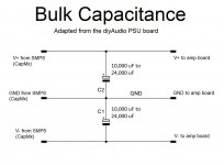
I suggest adding some bulk capacitance between the CapMx boards and the amp boards. About 10,000 uF to 24,000 uF will help with bass response and definition. In engine building the saying is "no replacement for displacement." In amp building that translates to no replacement for bulk energy storage.
Right, I have had single rail PSU in my head lately.
Separate bulk capacitor banks for +V to GND and GND to –V. For each channel of course. The point where the speaker return lead is connected is also important. Looks like you already have excellent low hum, so consider a way of making the GND connection of the extra bulk capacitance to the same point where you have your speaker return.
@TungstenAudio
Thank you again for the fine advice. I need to ask more questions before I commit to buying the components for the bulk capacitance.
Keeping in mind that the PSU is Switched Mode and there are two Cap Mx’s:
- Is all I need just 10,000 uF to 24,000 uF, i.e. a single cap for each VPOS and VNEG supply? If so, I can mount 4 caps on a board and do point-to-point connections.
- Or would a PI Filter as used in the DIYAudio Universal Power Supply be desirable, while I’m already using Cap Mx’s? If the answer is “yes”, then I might as well use a DIYAudio Universal Power Supply, but it’ll be quite expensive seeing that I’m in a different country.
A single cap for each rail (4 total) would be fine. I like the Kemet ALS70 series for this application, but you can certainly choose what is easiest.
The CapMx boards are hopefully reducing the ripple. The extra caps are for energy storage, so a Pi filter isn’t necessary.
The CapMx boards are hopefully reducing the ripple. The extra caps are for energy storage, so a Pi filter isn’t necessary.
A single cap for each rail (4 total) would be fine... The extra caps are for energy storage, so a Pi filter isn’t necessary.
Would you mind checking if the logic of this schematic is correct? I've adapted it from the diyAudio PSU board.
Attachments
Have started playing with a tube preamp in front of my M2. Is R2 arbitrary @100k to set the input impedance? Could I up that to 200-300k? Or is there more to it than that?
In my M2 clone, I added a 1R3 ohm resisitors in parallel with the original 0R47 source resistors to lower them to 0R345.
I simply removed them from the R2 positions and zeroed the output offset to try favoring the P-ch. It raised H2 to about the same level as H3 as seen in the measured spectrum.
I like the sound, more relaxed and spacious was my impression. I'll leave it like this for a while.
I need to get a twin-T notch filter built to look at the residual distortion in real time.
Cinco
Hi Cinco,
it is easier to download Diana a residual distortion program.
Here https://www.data-odyssey.nl/Diana.html
and maybe you have to write to Emond here
https://www.diyaudio.com/community/threads/diana-a-software-distortion-analyzer.315785/
to get the password to unzip the packed file-
Disable your virus program or write an exception for Diana in your virus program. Otherwise it will be deleted or located in quarantine.
It happened more than one time to me that the Spice residual program showed neg phase and In real with Diana it was just the opposite....
Thanks generg,
Alas, I got Diana a while back but my sound card doesn't work properly with card's ASIO driver (which Diana requires).
There is something they did outside of the ASIO specs and it's old now so no hope of a driver being properly written.
Someday maybe I will get a 2 channel recording interface by Focusrite or Motu.
Anyhow, I had a similar thought about simulation not matching real circuit behavior...
Real measurements needed.

 slowly training ears to hear the difference between positive and negative phase H2 though.
Alas, I got Diana a while back but my sound card doesn't work properly with card's ASIO driver (which Diana requires).
There is something they did outside of the ASIO specs and it's old now so no hope of a driver being properly written.
Someday maybe I will get a 2 channel recording interface by Focusrite or Motu.
Anyhow, I had a similar thought about simulation not matching real circuit behavior...
Real measurements needed.
slowly training ears to hear the difference between positive and negative phase H2 though.- Home
- Amplifiers
- Pass Labs
- Official M2 schematic