Oooo.....I like this combo...🙂
Easier to implement than a Schading. Just replace P-ch FET in my case 2SK1530 already soldered in the board.
Easier to implement than a Schading. Just replace P-ch FET in my case 2SK1530 already soldered in the board.
Attachments


didn't said it is Wild West Elixir ....... just said it is different
polarity - flip speakers
polarity - flip speakers
I have come to the conclusion that the slow DC offset drift I have on this M2 build of mine might very well come down to the IRF devices being faulty. Harris NOS types. Will replace them with modern Vishay types and report back.
The trouble I experienced with the M2 DC offset that was drifting was due to a blown IRFP9240. I am convinced the supplied Harris Mosfets are fake - or at least the P channels. The surface texture of the package looks suspicious.
The last bit of trouble I am encountering is a slight bit of hum - but it is not magnetically induced. I have moved the channel with heatsink away from the mains transformer and the hum level remains the same. It must be some ground loop issue - yet I have connected everything as per textbook.
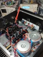
I had two copper ground connector planes made for the capacitor banks. Came out well.


The last bit of trouble I am encountering is a slight bit of hum - but it is not magnetically induced. I have moved the channel with heatsink away from the mains transformer and the hum level remains the same. It must be some ground loop issue - yet I have connected everything as per textbook.
I had two copper ground connector planes made for the capacitor banks. Came out well.

Hi
i build two M2:
What i do not understand is that both M2 have just 12dB gain??
i use the matched Jfets by diyaudio store. 6-8mA as recommended in M2 schematic
M2 IRFP = 11,8
M2_F Fairchild 12,15dB
Q1: is that because i have "just" 22.7V rail each?
configuration:
i made a normal IRFP M2 since may 2022 and i am happy with the sound. compared to a F5 lateral its a little bit less clarity butthe M2 try to build a deeper sound stage. some times its sounding a bit too round.
now i build the exactly same amp but with the fairchild N = FQH44N10...as tungsten audio recommend in ACA premium
and the PMOS FQA9P25.
the sound is much better , i "just" look as low Ciss,Crss etc. and lowRdson to get the bias high because of my 84dB 4R speakers. i do not look at the Xdunctanc for the first step.
i get with both degeneration resistors of 0,349R a bias about 1,8Amps @ 22,7V rail.
with 2,3Amps bias with 0,278mR the get to hot after 1 hour idle 90°C..😳
my psu consist of 2x300VA the secondary get parallel. CRC 66mF 4x0,47R 66mF.
i got NMOS VGS 3,55V PMOS Vgs 5,09V
with R13+R14 = about NMOS 4,15V PMOS 5,68 = 9,83V
kr chris
entire voltage gain of M2 is given solely by autoformer
what you have there is input buffer in front of autoformer, and following output buffer (feeding speakers)
both buffers are having some slight loss, so sliiiiightly less than 1V/V (0db)
autoformer is nominally 600R:15k
meaning voltage ratio of sec to primary being square root of impedance ratio, so 5V/V
in real life, there is also sliiiight loss, too
autoformer function, where secondary is stacked on top of primary, means that input is across primary (say 1), while output is taken across (primary+secodary) (that 1+5), and resulting gain is 1+5=6V/V, which is 12db
go figure


If i want top protect the Autoformer. Can in just use copperfoil and put it around it???
foil should bei grounded???
foil should bei grounded???
Interference. I know Prasi M2 PCB. Where he use the tektro shield but this is not fit to the official PCB.
I dunno, 12 dB gain seems low for the Edcors. Including losses, I would still expect at least 14 dB.
Interference. I know Prasi M2 PCB. Where he use the tektro shield but this is not fit to the official PCB.
external magnetic fields, only Ferrite material, including so called Mu-metal thingies
so, whatever you end with (improvise) mount it on Edcors, be sure to avoid shorts with pins, and connect shield with thin wire to nearest GND
... the tektro shield but this is not fit to the official PCB.
Although there is an "Official M2 Schematic" (post #1 in this thread), there is no "official M2 PCB". There's a tea-bag M2 PCB, and there's a diyAudio Store M2x PCB. and there's a Prasi M2 PCB, but none of these are "official".
Hi
i build two M2:
What i do not understand is that both M2 have just 12dB gain??
i use the matched Jfets by diyaudio store. 6-8mA as recommended in M2 schematic
M2 IRFP = 11,8
M2_F Fairchild 12,15dB
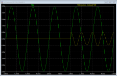
How did you measure the above?? Did you use an oscilloscope to look at the amplified sinewave? This measurement should be done with nothing connected to the output. The output sinewave will start to clip earlier due to slightly lower than desired supply rails. You'll be able to get an extra volt of 2 if your rails are around 24-25V loaded. The 2 X 20V AC secondary's transformer will get you there. This will allow the full gain ability of Edcores to reach the amp output, without being clipped by the low supply rails.
Last edited:
- Home
- Amplifiers
- Pass Labs
- Official M2 schematic