Normally a pair of 3W 2.2k resistors are used across the caps to drain the caps when the amp is turned off.
They aren't shown on the posted schematic but should be there.
You will see them in the earlier firstwatt schematics.
They aren't shown on the posted schematic but should be there.
You will see them in the earlier firstwatt schematics.
Last edited:
Next attempt.
Dual common cathode TO220 or TO247 diode.
Fischer Elektronik SK492 heatsink with THFU clamp.
Shunt realized with mounting ept 911-32006 power terminals.
Faston or wired cable connection.
JP
Do you know whether the heatsink has a coating which is electrically non-conducting?
If not, just need to add mica/grease or keratherm to each diode.

22€/20 batch.
JP
Could be worthwhile starting up a group buy thread.
I´m trying new PCB manufacturer and I expect today (or saturday) UPS delivery of 4 PCB´s (Pass Headphone Amplifier). I will then estimate the quality of this new one.
I´ll order 2 to 4 prototype before proposing GB.
JP
I´ll order 2 to 4 prototype before proposing GB.
JP
I´ll order 2 to 4 prototype before proposing GB.
JP
Hello JP64
Aluminium non soldering connection are week nodes for audio psu.
Copper wire solder directly to the board are rock solid connection ,
not made by mechanical contact's only.
SMD caps and resistors are fragile. They get old more quickly.
Throug hole component's are the best choice in my opinion but that only me 😀
Anyway you get talent for design stuff so please make more

Congratulations 🙂
Attachments


Salut @Soundhappy
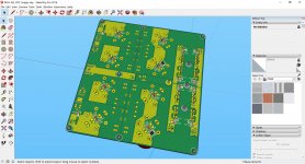
the vias are using in large quantity to connect ground planes on top and bottom side; using via filling would give you bare copper and this is in my opinion very important for audio power supplies. I´m using successfully this technology since 20 years for digital or analog power supplies
Do you´ve serious studies about THT vs SMD aging behavior? I´m using SMD technologie in telecom and military projects ( >10 years LC) since availability and without noticeable fealure rate.
You should apply complete coating to the board.
Notice, that the loaded components are right dimensionned and THT.
Since the connector is pressed in (gas-tight, best ever connection), you don´t need large eyed pads! This connector is one possibility: take a big soldering iron to connect both power planes (plated area) and big gauged cable (bad connection in my eyes).
DIY´er like to solder cable directly on pad of PCB, cheaper but quick dirty solution, only my opinion?
Merci pour les critiques, bonne fin de semaine.
JP
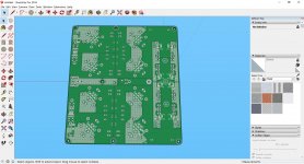
As mentionned, I´m waiting for PCB boards and will order PSU prototypes after quality evaluation of my new PCB manufaturer.
Boards will be equipped and tested, all reported in a test report, considering as FAI then complete documentation available.
After this, perhaps after some corrections, I´ll propose GB.
Nobody wants to buy "die Katze im Sack".
JP
Boards will be equipped and tested, all reported in a test report, considering as FAI then complete documentation available.
After this, perhaps after some corrections, I´ll propose GB.
Nobody wants to buy "die Katze im Sack".
JP
Hello JPSalut @Soundhappy
the vias are using in large quantity to connect ground planes on top and bottom side; using via filling would give you bare copper and this is in my opinion very important for audio power supplies. I´m using successfully this technology since 20 years for digital or analog power supplies
Do you´ve serious studies about THT vs SMD aging behavior? I´m using SMD technologie in telecom and military projects ( >10 years LC) since availability and without noticeable fealure rate.
You should apply complete coating to the board.
Notice, that the loaded components are right dimensionned and THT.
Since the connector is pressed in (gas-tight, best ever connection), you don´t need large eyed pads! This connector is one possibility: take a big soldering iron to connect both power planes (plated area) and big gauged cable (bad connection in my eyes).
DIY´er like to solder cable directly on pad of PCB, cheaper but quick dirty solution, only my opinion?
Merci pour les critiques, bonne fin de semaine.
JP
My point of vue is from my own diy audio not professional "expertise".
For example i get analog musical synthesizer's instrument's some vintage Roland and Korg with THT
and the modern SMD ones like Elektron or Dave Smith Instruments.
Old one work after 40 years and modern one's need reparations after 3 and 5 years. Sound very nice !
Well i am far from genaralise but that my personal experience with machines who use SMD compononents.
Probably not high military quality product's.
Me like large pads and big components i understand people who want try other construction options.
Have fun and nice week-end.
Thank You and best regards 🙂
Through hole components makes it simple to service/modify for back yard hack DIYers (that's us)
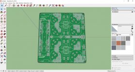
PCB only.
First modifications:
- bleeder resistor SMD or THT
- LED resistor SMD or THT
- bigger eyed wire solder pads
Replacing SMD capacitors with THT ones will need larger PCB (principaly for the rectifier diode snubber: SMD one was very nice to place)!
Is there a recommendation for film capacitors in parallel to electrolytic ones?
JP
Attachments
PCB only.
First modifications:
- bleeder resistor SMD or THT
- LED resistor SMD or THT
- bigger eyed wire solder pads
Replacing SMD capacitors with THT ones will need larger PCB (principaly for the rectifier diode snubber: SMD one was very nice to place)!
Is there a recommendation for film capacitors in parallel to electrolytic ones?
JP
Hi JP
That nice Diyers friendly boards.
Free components choice and wire, connectors type is cool options.
Film capacitors can be Vima brand polypropylene for example.
Very appreciated 🙂
PCB only.
First modifications:
- bleeder resistor SMD or THT
- LED resistor SMD or THT
- bigger eyed wire solder pads
Replacing SMD capacitors with THT ones will need larger PCB (principaly for the rectifier diode snubber: SMD one was very nice to place)!
Is there a recommendation for film capacitors in parallel to electrolytic ones?
JP
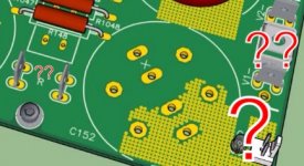
Kudos on your very nice PS layout! Might be good to have a bit more space between the stinking hot thermistor R165 and adjacent PE connector?
BK
Kudos on your very nice PS layout! Might be good to have a bit more space between the stinking hot thermistor R165 and adjacent PE connector?
BK
Pretty sure that is connection to earth not soft start thermistor.
So only hot for a short period of time under falt condition.
I think it will be fine.
Pretty sure that is connection to earth not soft start thermistor.
So only hot for a short period of time under falt condition.
I think it will be fine.
Ahh - good point!
BK
- Home
- Amplifiers
- Pass Labs
- Official M2 schematic