What would be a good replacement for the Panasonic ERX range of 3W resistors? They are getting hard to source. Especially around here.
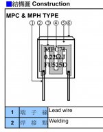
Interesting ones is metal plate MPC74 0.47 R | 5 watts made by Fukushima Futaba in Japan.
8 X FUKUSHIMA FUTA MPC74 0.47R 0.47 OHM 5W 10% NON-INDUCTIVE RESISTOR | eBay
Enjoy !
Interesting ones is metal plate MPC74 0.47 R | 5 watts made by Fukushima Futaba in Japan.
8 X FUKUSHIMA FUTA MPC74 0.47R 0.47 OHM 5W 10% NON-INDUCTIVE RESISTOR | eBay
Enjoy !
Thanks. I see RS now stock them.
I have try Panasonic and wire wounds and my prefered choice are MPC74 in source resistors position.
Mills brand non-inductive are interesting too but cost is high and not sure they sound like Futa 🙂
Have a nice day
Mills brand non-inductive are interesting too but cost is high and not sure they sound like Futa 🙂
Have a nice day
rest of them burry in backyard , and watch them grow
LSK matched pairs was scarce to get and i
 get lucky 8 mA Idss one set from four.
Btw total cost with shipping was more 200 $

Maybe i make gift to my younger brother so he diy with jfet's precious ring for his fiance.
Gold and diamonds are old fashion 😉
What the adaptation in jfet's circuit tricks for 6 |10 mA pairs ?
for 6: nuttin' - just toss them in without source resistors
for 10: nuttin' - just toss them in with , say, 15R source resistors
for 10: nuttin' - just toss them in with , say, 15R source resistors
Finaly got the time to start putting my M2 together. About to connect one of the chanels, to check if it does what it's supposed to do. Hopefully it's not the last picture before the fire alarm goes off... :0
https://www.dropbox.com/s/e9fl7d4wtgcn9mw/Foto%202017-04-15%2017%2026%2026.jpg?dl=0
https://www.dropbox.com/s/e9fl7d4wtgcn9mw/Foto%202017-04-15%2017%2026%2026.jpg?dl=0
Last edited:
nice, clean work.
[What is that 8 legged thing doing in there (on the floor)???]
Looks like a 6-legged thing to me, and it looks like it should be in the socket near it...
https://www.dropbox.com/s/8yjhidweibcmrkk/Foto 2017-04-17 20 41 45.jpg?dl=0
Up and (just about)running. 🙂 But, after having looked through all postings, I still can't figure out exactly how to meassure the offset? Or is it just too obvious how to...? :/
Up and (just about)running. 🙂 But, after having looked through all postings, I still can't figure out exactly how to meassure the offset? Or is it just too obvious how to...? :/
Last edited:
voltmeter between black and red speaker post
simple , isn't it ?
Thanks a lot Zen!
Thing is I was just thinking that maybe I was making things more complicated than they really are, so I was just testing that: Offset 0,4 mV 😀 And about 0,640 V at R13/R14.
My first build, so I'm very happy!!! 🙂
Thanks for all your help!
//Ronny
put lid on , leave it cooking , recheck both offset and Iq after temp equilibrium
though m M2 is extremely civil there , minimal difference between cold and hot state
did you checked sound yet ?
though m M2 is extremely civil there , minimal difference between cold and hot state
did you checked sound yet ?
for 6: nuttin' - just toss them in without source resistors
for 10: nuttin' - just toss them in with , say, 15R source resistors
Thanks Zen Mod
 🙂
🙂Attachments
- Home
- Amplifiers
- Pass Labs
- Official M2 schematic


