For Transformers, I got this one:
AS-4218 - 400VA 18V Transformer - AnTek Products Corp
The delta on the 300va is about $10, so I paid the extra.
I'm using the ChipAmp Board, although I did a point to Point based on the diagram in the F5 manual for another project.
Dave
AS-4218 - 400VA 18V Transformer - AnTek Products Corp
The delta on the 300va is about $10, so I paid the extra.
I'm using the ChipAmp Board, although I did a point to Point based on the diagram in the F5 manual for another project.
Dave
Images ....
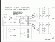
This is the schematic that I used:

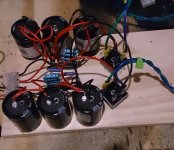
This is the point to point, used a tag board, the .47R are in a 3D ladder, and the 2.2K is on the other terminals. Used 600V wire that I will be using in a tube amp project, probably over kill, Caps are 22K uf.
While while you cannot see it, the thermisistors and the cap are in the screw terminals on the 110 side of the transformer.

Dave
This is the schematic that I used:

This is the point to point, used a tag board, the .47R are in a 3D ladder, and the 2.2K is on the other terminals. Used 600V wire that I will be using in a tube amp project, probably over kill, Caps are 22K uf.
While while you cannot see it, the thermisistors and the cap are in the screw terminals on the 110 side of the transformer.

Dave
Q6 and Q7 are LM385-1.2
D1,D2,D3 are 1N4148
Q5 4N35
yeah , stick it to the wall and enjoy sheer beauty
If I am getting too much voltage across R13,R14 - what lowers this, is it R11? Go lower or go high?
If I am getting too much voltage across R13,R14 - what lowers this, is it R11? Go lower or go high?
R11 influences the current through the optocoupler.
If you go down, current goes up, optocoupler becomes more conductive and drops less voltage.
R11 influences the current through the optocoupler.
If you go down, current goes up, optocoupler becomes more conductive and drops less voltage.
and drops more voltage through R6(+P1) and R7 , thus strangling mosfets
what's exactly too much ?
I am measuring 1.5 volts across the source resistors before I have to turn the thing off. It takes a minute or two to get up that high, I believe that is functioning as designed. Could be another problem going on too, but it doesn't appear to be a short, it's ramping up too slowly for that, and variac aint buzzing. I have some CNY17 opto-couplers as well, if this may change things.
It takes a while to charge C3. Only when you reach Vgs(on) for both MOSFETs you will start to see voltage across R13,14.
If you see the voltage over C3 rise and then level the o/c seems to work.
If you see the voltage over C3 rise and then level the o/c seems to work.
Tea - both channels , or just one ?
Both channels. I used this 4N35, 220R R11, but maybe I need to double check that.
http://www.vishay.com/docs/81181/4n35.pdf
It's possible there is a flaw in my board too.
well , triple check that (parts and pcb)
schematic is so simple and more than proven
Works now - lesson of the day, dont put the optocoupler in backwards.


So it was coupleropto.....🙂
No, it was just me being me. The opto had no role in it. 😉
Is anyone making (and selling) circuit boards? I want a pair! 🙂
Nope! Maybe someday or never....😡
Is anyone making (and selling) circuit boards? I want a pair! 🙂
Nope! Maybe someday or never....😡
I am working on a set with UMS spacing. I have one channel working, and one not so far. I am still debugging the other channel to see if I have a bad part or a design flaw somewhere, or I simply toasted one of my transformers. Still need to troubleshoot it more.
I am working on a set with UMS spacing. I have one channel working, and one not so far. I am still debugging the other channel to see if I have a bad part or a design flaw somewhere, or I simply toasted one of my transformers. Still need to troubleshoot it more.
Wonderful news! I hope that this one will be the real thing! I will cross my fingers and send out some prayers!!! 😀😀😀
- Home
- Amplifiers
- Pass Labs
- Official M2 schematic
