Hi!
Is the 2SK1529/200 too wimpy?
Greets:
Tyimo
Hi
You can get 2SK1503 & 2SJ201 which more powerful here
Tech DIY Company Store
Greetings
Nice case, skylab. Where is it from?
And: spencer has the jfets: Store FET Audio | Hi-End Audio Projects
I found this from a taobao shop at around usd110 without shipping.
C3 voltage
Elna Silmic II 3300uF are available only for 10V. Is it sufficient voltage?
3300uF/16V sufficient
Elna Silmic II 3300uF are available only for 10V. Is it sufficient voltage?
on the verge
use any decent electrolytic with minimum 16V voltage , bypassed or not with , say, 1uF solid cap
use any decent electrolytic with minimum 16V voltage , bypassed or not with , say, 1uF solid cap
on the verge
use any decent electrolytic with minimum 16V voltage , bypassed or not with , say, 1uF solid cap
Roger that. Thanks!
... GB is coming...
After a lot of ordering problems, I´m finally delivered next week (I´ve try about 5 manufacturers: cost gets high then the PCB consists in a lot of vias and price target should be not more then 15€).
Please be patient...
Jean-Paul
After a lot of ordering problems, I´m finally delivered next week (I´ve try about 5 manufacturers: cost gets high then the PCB consists in a lot of vias and price target should be not more then 15€).
Please be patient...
Jean-Paul
... GB is coming...
After a lot of ordering problems, I´m finally delivered next week (I´ve try about 5 manufacturers: cost gets high then the PCB consists in a lot of vias and price target should be not more then 15€).
Please be patient...
Jean-Paul
Great news!
... GB is coming...
After a lot of ordering problems, I´m finally delivered next week (I´ve try about 5 manufacturers: cost gets high then the PCB consists in a lot of vias and price target should be not more then 15€).
Please be patient...
Jean-Paul
That's great news.
Thanks
Just a question ,
since I did find a pdf M2 schematic and there there is a different
connection for the opto isolator ....
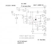
Can someone confirm that the 4N35 is connected through pins 1 , 2 , 4 and 5 ?
Thanks
since I did find a pdf M2 schematic and there there is a different
connection for the opto isolator ....
Can someone confirm that the 4N35 is connected through pins 1 , 2 , 4 and 5 ?
Thanks
Not sure I understand your question.
The data sheet shows the relevant contacts at
1 Anode
2 Cathode
4 Emitter
5 Collector
Have you come across a different pin-out?
The data sheet shows the relevant contacts at
1 Anode
2 Cathode
4 Emitter
5 Collector
Have you come across a different pin-out?
Nope , not a different pin-out in se butNot sure I understand your question.
The data sheet shows the relevant contacts at
1 Anode
2 Cathode
4 Emitter
5 Collector
Have you come across a different pin-out?
in post #39 http://www.diyaudio.com/forums/pass-labs/281520-official-m2-schematic-4.html#post4495117
there is a pdf with , I guess , an error on the schematic .It make use of the Base ( pin 6 ) instead of the Collector ( pin 5 )
BTW no problem . I did already build a prototype and it works like a charm .
Nice sound .... and next days probably the other channel .
I did notice the PSRR being lower than the F5 . Should I look at a regulator or C-R-C-R-C until I am satisfy ?
Nope , not a different pin-out in se but
in post #39 http://www.diyaudio.com/forums/pass-labs/281520-official-m2-schematic-4.html#post4495117
there is a pdf with , I guess , an error on the schematic .It make use of the Base ( pin 6 ) instead of the Collector ( pin 5 )
Well spotted. That is an error that has since been corrected by Jean-Paul in post #159
Yes, but what about R1-2?
Depends on what you want to use to drive the output. Without the transformer you have no gain.
Would there be an advantage to replacing R3 and R4 with a 200 ohm P2 as in the most recent versions of the F5 to adjust offest to minimal distortion?
Can anyone point me to the referenced F5 design and enlighten me why it would be 200 Ohms and not 20?
Is there a pedestrian procedure how to adjust to minimal distortion apart from my stellar hearing? Or is it simply adjusting to have DC vanish?
200 is oomphteen times more than needed and required , at least if we are talking about source resistors in input JFet buffer stage
if you're keen of setting precise output offset fo buffer itself , replace R3 and R4 with 20R trimpot , not 200R
if you're keen of setting precise output offset fo buffer itself , replace R3 and R4 with 20R trimpot , not 200R
- Home
- Amplifiers
- Pass Labs
- Official M2 schematic