yes , it is
that will decrease Iq , of course , and increase output impedance , and decrease A class power
OKay .
🙂
One more thing , regarding the N channel Mosfets ; I did build the amps ,working perfectly with the Fairchild IRFP9240 ( as with the F5 ), but I have also a couple of IR ...Just wondering if on the M2 the IR's can make slight difference or not .
Thanks
Aaron from Don-audio says the trannies have arrived and are shipping now.
Yay!
Yap! 🙂 😀
By the way mine jfets have IDSS around 6.6mA. Do I need to decrease the source resistance?
No 6.6 mA is fine, it's just a buffer
I have 10 cans 22mF each coming for the PSU.
How shall I combine them for the filters of the two rails?
rectifier-CCRCCC-amp
rectifier-CCCRCC-amp
or even
rectifier-CRCCCC-amp
rectifier-CCCCRC-amp?
How shall I combine them for the filters of the two rails?
rectifier-CCRCCC-amp
rectifier-CCCRCC-amp
or even
rectifier-CRCCCC-amp
rectifier-CCCCRC-amp?
I have 10 cans 22mF each coming for the PSU.
How shall I combine them for the filters of the two rails?
rectifier-CCRCCC-amp
rectifier-CCCRCC-amp
or even
rectifier-CRCCCC-amp
rectifier-CCCCRC-amp?
Try to simulate whit psu tool! I would use 5x22mF-R-5x22mF.
But if you have only 5 per rail then 2x22mF-R-3x22mF!
I also have 22mF in my psu. I choose 1x22mF - L - 3x22mF!
Last edited:
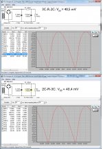
When I tried LTSpice and simply configured a CRC filter adding capacitance after the resistor had more impact on attenuation at 50Hz than in front.
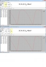
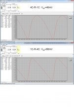
PSU Designer II from Duncan's Amp Pages actually gives a different picture (Vpp)
2C-R-3C 50mV
3C-R-2C 40mV
1C-R-4C 90mV
4C-R-1C 46mV
PSU Designer II from Duncan's Amp Pages actually gives a different picture (Vpp)
2C-R-3C 50mV
3C-R-2C 40mV
1C-R-4C 90mV
4C-R-1C 46mV
Attachments
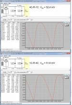
Try it again with correct Cap ESR.
I like ltspice cause I can do dynamic loading not just static loading, or any other scenario that I can think of.
I like ltspice cause I can do dynamic loading not just static loading, or any other scenario that I can think of.
Last edited:
When you arrange caps in parallel, effective ESR drops.Just downloaded LTSpice and need to learn e.g. how to do "dynamic loading" (can you expand, pls?)
Caps are Panasonic TS-UP ECOS1EP223CA and the ESR I find in the sheet is 0.029Ohm@120Hz. In the sim I put 30mOhm. Where is my mistake?
Two caps in parallel: 1/R = 1/30 + 1/30
R = 15mOhms
3 caps in parallel will be 10mOhm etc
If your speakers are considered a difficult load, then CCCCRC ie with single cap at output will potentially give much worse ripple as well as voltage drops on dynamic loading depending on speaker impedance and sensitivity.
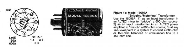
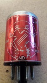
Altec 15095A
Hi. I have a couple of these lying around and was wondering if they could be used in the front end of the M2. I've attached a couple of pictures of the Altecs hoping for suggestions on proper hook-up. I've already put together a pcb in diptrace that I posted if anyone would like to look through it to see if it makes sense. Thanks.
Hi. I have a couple of these lying around and was wondering if they could be used in the front end of the M2. I've attached a couple of pictures of the Altecs hoping for suggestions on proper hook-up. I've already put together a pcb in diptrace that I posted if anyone would like to look through it to see if it makes sense. Thanks.
Attachments
- Home
- Amplifiers
- Pass Labs
- Official M2 schematic