... GB is coming...
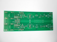
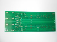
After a lot of ordering problems, I´m finally delivered next week (I´ve try about 5 manufacturers: cost gets high then the PCB consists in a lot of vias and price target should be not more then 15€).
Please be patient...
Jean-Paul
How are things proceeding? Take your time, no chassis for me to buy in DIY store, have a few amps waiting for their arrival.
Russellc
From my side I have all the parts waiting for mounting! No news from PCB board! I guess its holiday time and no one wants to play whit their toys...OR?
For all the Greedy Boyz,
😎
Thank you Mr. Pass for your generosity!
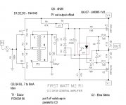
Simplicity is the ultimate sophistication...as they say!! Such a simple and clever design!
I've been speculating about the schematic for months now, and I thought it was was going to be something along the lines of the attached.
I did scratch my head too when I first saw the schematic. Initially though that the diodes were biasing zeners and the optocoupler served as some sort of limiter circuit.

Attachments

In my data sheet the third pin is also not connected inside the package.
I saw this : http://www.ti.com/lit/ds/symlink/lm185-adj.pdf
general/common FW jobie - look F4 ,F5 for example
2x18Vac secondaries , two bridges , CRC cap bank
2x18Vac secondaries , two bridges , CRC cap bank
Initially though that the diodes were biasing zeners and the optocoupler served as some sort of limiter circuit...
...not sure what I was thinking... the optocoupler does serve as a current limiter...
I have been staying awake at night thinking about the optocoupler.... now I am not sure what it does.... is it there for setting the bias?

I was just wondering if there is a possibility that diyaudio store would step in
to make the PCB for the M2?????
I think a lot of folks out there have already the parts and want to solder!!! If the guy who wanted to
make a group buy changed his mind he should tell us....!!!
to make the PCB for the M2?????
I think a lot of folks out there have already the parts and want to solder!!! If the guy who wanted to
make a group buy changed his mind he should tell us....!!!
- Home
- Amplifiers
- Pass Labs
- Official M2 schematic