no , connect input to pin7
As always, I don't understand your answer 😀
That's why it took some while for this post, to think it over....😱
What to do with pin 1 and 5 then?
is this a way the trafo can be represented in a different way, how papa used it?
Attachments
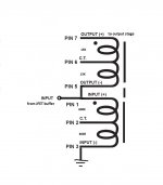
sorry , 'twas a typo - what I meant - connect input to pin 6
usually , not using entire (all) winding(s) in xformer is not so clever
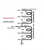
I wrote proper impedances and proper voltage ratios for Edcor 600/15K
for signal connected to pin 6 , calc. resulting gain with simple proportion
usually , not using entire (all) winding(s) in xformer is not so clever
I wrote proper impedances and proper voltage ratios for Edcor 600/15K
for signal connected to pin 6 , calc. resulting gain with simple proportion
Attachments
Project Sandroller
Let me introduce you to my project that I call Sandroller.
It started with my idea of building a tube amp. But none of the designs I saw appealed to me, mostly b/c I didn't want to electrocute myself. Then I stumbled over the freshly published M2 design with no F/B. I considered that to be toobey enough for me and looked into it. Reading around I saw that with the parts for the M2 I could almost also build an F5. So I figured I build both. In addition, I read about different MOSFETS and how they sound different. So I got myself some FQA (thanks Generg!) and some Toshibas (thanks NicMac!) and want to be able to switch between them.
Out comes the Sandroller for which you find attached the schematic and left and right proto board layouts. The idea is to connect the MOSFETs to the board via 10 pin connectors and to choose between F5 and M2 by plugging a 6 pin connector into the JFET stage. NTC and source resistors are soldered directly to the MOSFETs. Pins on the boards are labelled where they go into the connectors.
Comments solicited.
Attachments
Complex project that way...especially because F5 and M2 has very different output stages. I find it much easier to swap whole PCB's in a chassis.
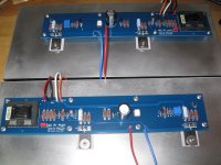
Following up on my last post, I assembled both PCBs and mounted them on a pair of Conrad heat sinks. I used a regular First Watt style PSU and listened to the M2 clone for about 16 hours on Friday, Saturday and Sunday.
http://www.diyaudio.com/forums/attachment.php?attachmentid=524431&stc=1&d=1452574993
It did not take that long to determine the amplifier was working properly. It is just that it sounds really, really nice, without being in-your-face about anything.
The Aleph J and the F5 have characteristics that I noticed the first time I heard them. The M2 does everything right and grows on you. The hardest part was to turn it off each evening.
Attachments
Oh well, I really was interested in J-P's boards as they follow the drill pattern of the Deluxe Diy Store pre-drilled heat sinks. I guess this box of parts is shelved for now.
On a more positive note, I was one of the first Beta customers of the new DiyAudio store and have a rear parts kit shipping to me domestically, and just got word the Deluxe 4U chassis and milled handles has been shipped from Italy. So, while M-2 is on hold for lack of boards, F-6 can at least resume.
Hopefully Jps1964 will return with the group buy on his boards😕
Russellc
sorry , 'twas a typo - what I meant - connect input to pin 6
usually , not using entire (all) winding(s) in xformer is not so clever
I wrote proper impedances and proper voltage ratios for Edcor 600/15K
for signal connected to pin 6 , calc. resulting gain with simple proportion
Thanks ZM!
I've tried input to pin 6 and gain is indeed much reduced 🙂 I'll try measuring with AC voltmeter what the gain is.
How do I calculate? I would think when input connected to pin6 I will get: 5 : (5+1+1) at the output, so 5/7 * Vin= attenuation 😕
Why do they call it 600/15k trafo and the impedance you wrote are all 4 times lower?
M2 sounds very, very nice with headphone output stage🙂
Following up on my last post, I assembled both PCBs and mounted them on a pair of Conrad heat sinks. I used a regular First Watt style PSU and listened to the M2 clone for about 16 hours on Friday, Saturday and Sunday.
http://www.diyaudio.com/forums/attachment.php?attachmentid=524431&stc=1&d=1452574993
It did not take that long to determine the amplifier was working properly. It is just that it sounds really, really nice, without being in-your-face about anything.
The Aleph J and the F5 have characteristics that I noticed the first time I heard them. The M2 does everything right and grows on you. The hardest part was to turn it off each evening.
Very clean and nice designed PCB!!! Shame it doesnt fit to standard case specs...🙁
Otherwise If you could alter the design to meet the UMS specs I imagine this would be one of the biggest group buys ever..🙂
It did not take that long to determine the amplifier was working properly.
4 boards for me, with cheese please🙂
Hi ,
is there any special reason , that R3, R4 source resistors must be 10ohm ?
Borbely in his kits usually used 50ohm trimpot which corespond with source resistors in range 22-33 ohm.
Increasing R3,R4 up to 22-27 ohm and usage input jfet with idss 8-9mA will increase dramatically distortion numbers ????
Very clean and nice designed PCB!!! Shame it doesnt fit to standard case specs...🙁
Otherwise If you could alter the design to meet the UMS specs I imagine this would be one of the biggest group buys ever..🙂
You can request chassis customization and ask that the holes match the M2 PCBs. I can provide the exact measurements.
You can request chassis customization and ask that the holes match the M2 PCBs. I can provide the exact measurements.
That's a great idea. BTW, congratulations on your PCB and build.
The M2 is quite the sleeper.
Cheers,
Dennis
You can request chassis customization and ask that the holes match the M2 PCBs. I can provide the exact measurements.
Yes, thats also an alternative only if you will make your PCBs available??? GB???
Let us know...
What is the impedance to be used on the trafo?
Found out:600-15K....
Group buy
Those interested in purchasing DIY First Watt M2 clone PCBs please access the Google document below an enter your DIYAudio name and number of sets desired. A set is one Left channel PCB and one Right channel PCB, proper to build one stereo unit. Each PCB measures 280mm x 52 mm, with mounting holes spaced at 90mm horizontally and 40mm vertically.
Be aware that PCB dimensions and mounting holes location DO NOT COMPLY with the diyAudio Universal PCB & Semiconductor Mounting Specification (UMS). However, since the chassis now allow customization, ordering one with pre-drilled holes in different positions may be possible.
https://docs.google.com/spreadsheets/d/1l9iTSRqvRB-aQRylz7Bw6E57BqXU4Pd6okGO8qfkttM/edit?usp=sharing
How long will be the GB open?
Can you post the PCB layout whit the correct dimensions?
- Home
- Amplifiers
- Pass Labs
- Official M2 schematic