Wow, I might have had one thing right, so I assume using a 20 ohm pot to null out DC at Edcores input will zero the DC there, but also at amps outputs? I don't get that, and a million other things!
Thanks,
Russellc
nope
whatever you do with DC level in front of Edcor , there is Elna Silmic between Edcor and OS
nope
whatever you do with DC level in front of Edcor , there is Elna Silmic between Edcor and OS
Sorry, not making myself clear, What I mean to ask is the use of the 220uf that mark's design contemplates wont end dc at the speaker taps will it? The original pot from PAPA's schematic will have to bring that to zero, right? or No?
Russellc
Sorry, not making myself clear, What I mean to ask is the use of the 220uf that mark's design contemplates wont end dc at the speaker taps will it? The original pot from PAPA's schematic will have to bring that to zero, right? or No?
Russellc
Yes. My understanding is that 220uF cap will just remove any DC at Edcor input. You still have to use the original pot to bring the offset down to zero at the output of the amp.
Sissychange in ZM Engrish? 😛practically , with just pot twirling on a JFET unity gain buffer , THD changes are diminutive...
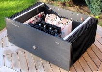
My M2 clone
More images here: Do It Yourself Audio Projects | First Watt M2
It plays music and sounds great, first impression - very dynamic with strong bass. I hear a bit of buzzing with my ear by the speaker, will have to put some screening around transformers...
More images here: Do It Yourself Audio Projects | First Watt M2
It plays music and sounds great, first impression - very dynamic with strong bass. I hear a bit of buzzing with my ear by the speaker, will have to put some screening around transformers...
Attachments
Nice ! Regarding buzzing, in my M2 I got rid of all noise by turning the trafos. So that the trafo output wiring was as far from the input trafos as possible.
Last edited:
Nice ! Regarding buzzing, in my M2 I got rid of all noise by turning the trafos. So that the trafo output wiring was as far from the input trafos as possible.
Thanks. Unfortunately I can't really turn the trafors, wires are too short...
More images here: Do It Yourself Audio Projects | First Watt M2
It plays music and sounds great, first impression - very dynamic with strong bass. I hear a bit of buzzing with my ear by the speaker, will have to put some screening around transformers...
Got a part number on your off-on switch there? Nice looking amp!
Russellc
Got a part number on your off-on switch there? Nice looking amp!
Russellc
Thanks. Not sure, I reused the switch (and chassis) from an older project, but I think it is this one: 693-1241.6821.1120 (Mouser part number)
Thanks. Not sure, I reused the switch (and chassis) from an older project, but I think it is this one: 693-1241.6821.1120 (Mouser part number)
Thanks! I like the look of it, and I noticed you had the 10mm front panel and it is long enough to go through.
Russellc
Last edited:
Hi, I am thinking to modify the M2 schematics to serve as a preamp. The target output voltage will be about 6VRMS and 2VRMS (two candidates for different system setups and final decision will be made after comparison).
What fets would your kindly suggest to replace the orignal M2 fet complementary pair to suit my need? J310? 170BL? Or anything great and easily available? Thanks.
What fets would your kindly suggest to replace the orignal M2 fet complementary pair to suit my need? J310? 170BL? Or anything great and easily available? Thanks.
If you're starting over you could consider replicating the stage1 function ("unity gain buffer capable of driving 600 ohm load") using a different circuit design. One possibility that has worked for me, is an IC opamp configured as a unity gain buffer, with or without a current booster. {Norwood and Tucson respectively}. Or you could try a BJT diamond buffer {Austin}, or perhaps a J112 source follower with a current booster {Mountain View}. I've used them all and they got the job done beautifully, in my opinion.
Since you plan to "modify the M2 schematics" keep in mind that you do have the option to discard complementary JFETs entirely.
Since you plan to "modify the M2 schematics" keep in mind that you do have the option to discard complementary JFETs entirely.
Hi, Mark,
Thanks. Yes I am open to all voltage follower possibilities. But I suppose that the complementary source / emitter follower gives lower distortion? So I thought maybe I would simply look for FET replacement in the M2 circuit and then do some simulation.
Anyhow, I will look into the circuits you suggests. Thanks again.
W. YAN
Originals were from Toshiba but matched replacements manufactured by Linear Systems currently available from diyAudio Store perform adequately....What fets would your kindly suggest to replace the orignal M2 fet complementary pair to suit my need? ...
Not necessarily correct. When lower distortion is desired, either the Tucson or Norwood input module that Mark Johnson designed for the M2X shows high potential to deliver. Sonic impression and your personal preference however, obey different set of rules altogether.... But I suppose that the complementary source / emitter follower gives lower distortion? ...
Last edited:
Hi, Indra1,
Thanks for the advice. I did a search and there are a lot of preamp circuit involving 170/74 pair as the final stage. However, the replacement price by Linear Systems is not really favorable. Therefore I am still looking for more affordable replacements. I will look into the Tucson and Norwowd module. Cheers.
W. YAN
Ignore my previous posts in this page. Apparently they belong to another one of the numerous "170/74 replacement" posts. Thanks.
I had a catastrophe because of a dry joint on the optocoupler, I saw smoke coming up from the board but can't figure which component it was. At that time, the voltage across the source resistor went up to about 1.7V. After doing a solder reflow, I managed to get the channel up and running but at a lower voltage, 0V555 versus 0V572 on the other.
I know its working somewhat, but for the long term reliability and ease of mind, what should I think of replacing with new parts?
I know its working somewhat, but for the long term reliability and ease of mind, what should I think of replacing with new parts?
Last edited:

- Home
- Amplifiers
- Pass Labs
- Official M2 schematic