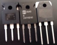
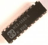
Yep; judging by the date-codes on my parts and yours, it happened sometime between 1991 and 1994.
Interesting. 1996 date-code with old logo.
Makes me wonder if the first one you posted (948) isn't the 48th week of 2009, rather than 8th week of 1994.
Makes me wonder if the first one you posted (948) isn't the 48th week of 2009, rather than 8th week of 1994.
Interesting. 1996 date-code with old logo.
Makes me wonder if the first one you posted (948) isn't the 48th week of 2009, rather than 8th week of 1994.
Thanks Jeff interesting interpretation.
So is 3 digits date code.
48 is the last week of the year

Interesting. 1996 date-code with old logo.
The logo change most likely occurred at the time when Harris decided to sell its commercial and military semiconductor product lines, which happened in 1998.
The IRFP9240s I have display the newer italicized "H" and have manufacture date code: 9840.
Tea-Bag response about newer Harris version
GB Pass M2 Clone Boards with 120mm UMS spacing by Tea-Bag
Is OK
GB Pass M2 Clone Boards with 120mm UMS spacing by Tea-Bag
Is OK

I have a couple Harris IRFP9140 with date code of 9540 that looks like
the middle one in post #2183 by Soundhappy. Got it for the original
Zen amp from Mouser around 1996.
the middle one in post #2183 by Soundhappy. Got it for the original
Zen amp from Mouser around 1996.
My problem I was having a couple pages back is solved! Everything on the non-functioning channel, er, I should say non-correctly-functioning channel, checked out OK. I went ahead and removed the LM385s, removed all the solder with braid, cleaned pads, and very very carefully replaced them. Fired it up and it worked perfectly! I defiantly couldn't see it, but I guess I had a teeny weeny bridge on one of those devices. Now both channels warm up slowly and sit rock solid stable at 1.3A, plus or minus a small handful of milliamps. Now I just need to adjust a couple resistor values to sort out the offset, then I'm off to the races!
Thank you Mr. Pass for the design, Grimberg for the excellent PCBs, and everyone who contributed their time and expertise to this thread! I can't wait to have a listen!

Thank you Mr. Pass for the design, Grimberg for the excellent PCBs, and everyone who contributed their time and expertise to this thread! I can't wait to have a listen!

The offset issue has been discussed above but, as a reminder, verify the polarity of the DC offset. If negative, increase the value of R7. In my case it got stuck around -50 mv. I resolved it by replacing R7 with a 49.9K resistor.
Same, I've ended up with negative offset on both channels right around -100mV. One channel I have pretty much sorted out by increasing R7. I went up to 56.2k which was far too much, rookie mistake I guess. I ended up paralleling it, with clip leads, with a 500k resistor which lands me at about 50.5k, essentially the same as your 49.9k. I was able to zero that channel, so I'll do the same with the other and I should be good to go!
Just to be clear, it is my understanding that the outputs Teabag has, (but I do have an inquiry to him) is that these are not Harris pairs, but a combination of Harris on one side, and Vishay on the other.
http://www.diyaudio.com/forums/grou...-120mm-ums-spacing-tea-bag-6.html#post5119124
Russellc
http://www.diyaudio.com/forums/grou...-120mm-ums-spacing-tea-bag-6.html#post5119124
Russellc
... but a combination of Harris on one side, and Vishay on the other....
That's what I use too. It's only the IR/Vishay P-channel parts that have the linearity glitch.
Cheers,
Jeff.
Mine uses Vishay FETs in both positions, I suppose time will tell if I'm disappointed with that choice 😉
I went home over lunch, slung some solder, and fired up both channels to "burn in" while I ate. Back downstairs about 30 minutes later, everything was nice and toasty, and I was able to easily null the offset on both channels. Unfortunately I had to return to work, otherwise I would be listening right now! Seems like tonight will be the night I do some final checks and hook everything up. It's going to be a long 4 hours until I'm off work 😀
Quick question, curiosity more than anything, is it normal for the offset to bounce around a little bit? Now, by bounce around I'm talking +/- 0.0005V or so, absolutely nothing I'm worried about. Like I said, curiosity.
Happy listening everyone!

- Home
- Amplifiers
- Pass Labs
- Official M2 schematic


