There are several points to sucess to make LYNX 3.0
First, C 101 and C109 is removed, and the second, the new capacitor (Cnew)is needed.
C101 is a kind of high cut filter (low pass filter) but its presence makes LYNX very unstable and reults oscillation almost always.
There are 2 kinds of oscillation waves. Around 2 MHz and around 200~300kHz.

The 2 MHz oscillation wave is about 2 Volts (in my memory, 4 v p-p) and behaves as mild form. The 200~300 kHz oscillaiton looks like sqare wave, is more critical, has very high voltage and always fries many transistors (Q105, Q106, Q107, Q110, Q111) and resistors (see below schematics and figures). I could catch a snapshot just before turning off power switch (using both hands).


C109 is located in feedback circuit but it makes LYNX also unstable. Unstability means it manifestes various unusual phenomena,example, even the "Pre-test" passed but after the output transistors wiring, abrupt oscillation is developed, and another example is that oscillation is developed when decreasing bias voltage (maybe because of change of output transistor contribution?) I performed many trials with the values of C 101 and C109, from 0pF to 330pF, I reached the conclusion that it is best when both capacitors (C101and C109) are abscent!

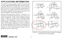
Cnew is between pin 2 and pin 6 of OP amp. Acording to OPA627 datasheet they recommend some capacitors for stabilty.

Other DIYer, BV also mentioned it in this thread. You also applied it in OPA134.
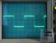
The best value of Cnew is around 1,000pF (below figures). C102 and C103 value are 5pF.
Below the level of 220pF of Cnew, it also produce oscillation.


I wish my experience could be a help to other DIYer.
And also wish I can see your schematics in your site again.
Thanks for your effort to introduce original, very great sound-producing LYNXs amp.
First, C 101 and C109 is removed, and the second, the new capacitor (Cnew)is needed.
C101 is a kind of high cut filter (low pass filter) but its presence makes LYNX very unstable and reults oscillation almost always.
There are 2 kinds of oscillation waves. Around 2 MHz and around 200~300kHz.
An externally hosted image should be here but it was not working when we last tested it.
The 2 MHz oscillation wave is about 2 Volts (in my memory, 4 v p-p) and behaves as mild form. The 200~300 kHz oscillaiton looks like sqare wave, is more critical, has very high voltage and always fries many transistors (Q105, Q106, Q107, Q110, Q111) and resistors (see below schematics and figures). I could catch a snapshot just before turning off power switch (using both hands).
C109 is located in feedback circuit but it makes LYNX also unstable. Unstability means it manifestes various unusual phenomena,example, even the "Pre-test" passed but after the output transistors wiring, abrupt oscillation is developed, and another example is that oscillation is developed when decreasing bias voltage (maybe because of change of output transistor contribution?) I performed many trials with the values of C 101 and C109, from 0pF to 330pF, I reached the conclusion that it is best when both capacitors (C101and C109) are abscent!
Cnew is between pin 2 and pin 6 of OP amp. Acording to OPA627 datasheet they recommend some capacitors for stabilty.
Other DIYer, BV also mentioned it in this thread. You also applied it in OPA134.
The best value of Cnew is around 1,000pF (below figures). C102 and C103 value are 5pF.
Below the level of 220pF of Cnew, it also produce oscillation.
I wish my experience could be a help to other DIYer.
And also wish I can see your schematics in your site again.
Thanks for your effort to introduce original, very great sound-producing LYNXs amp.
Last edited:
I forgot to mention the test square wave in oscilloscope screen.
It's 10kHz square wave.
Thanks again, Jan.
It's 10kHz square wave.
Thanks again, Jan.
#660 figures
There are critical errors in image loadings in Post number #660 and #661.
I feel really sorry for inconvenience.
But you can see the files by mouse right clicking and saving image ("Save target as...") in post #660 directly.
I attach the image files of #660.
There are critical errors in image loadings in Post number #660 and #661.
I feel really sorry for inconvenience.
But you can see the files by mouse right clicking and saving image ("Save target as...") in post #660 directly.
I attach the image files of #660.
Attachments
Last edited:
#661 Figures (1st~6th)
I attach the image files #661 (1st~6th).
You can also see the files by mouse right clicking and saving image ("Save target as...") in post #661 directly.
I attach the image files #661 (1st~6th).
You can also see the files by mouse right clicking and saving image ("Save target as...") in post #661 directly.
Attachments
-
 1_120212_From OPA627 datasheet.jpg296 KB · Views: 545
 -
 1_Trial of various value_1.jpg484.2 KB · Views: 772
 -
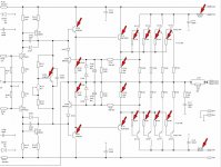 120212_Fried devices in schematic.JPG107.4 KB · Views: 907
 -
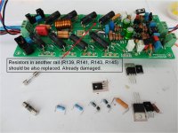 120212_Fried devices in board.JPG174.8 KB · Views: 595
 -
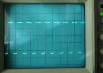 1_250kHz oscillation.jpg280.6 KB · Views: 303
 -
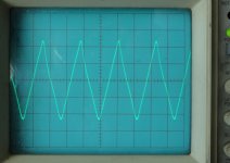 1_2MHz oscillation.jpg225 KB · Views: 472
Last edited:
#661 Figures (7th ~14th)
I attached the image files of #661 (7th~14th)
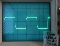
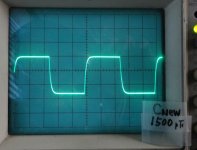
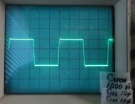
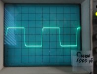
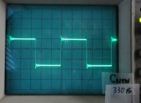
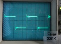
All images are the result of 10kHz square wave input.
The value of Cnew (between pin 2 and pin 6 of OPA627) is marked in each image. You can also see the C102 and C103 values in the image.
I think the 1000pF (with C102 and C103 5pF) image is the best looking figure.
Cnew value 220pF was the threshold (I see severe ringing).
Below the 220pF, oscillation occurred.
I attached the image files of #661 (7th~14th)
All images are the result of 10kHz square wave input.
The value of Cnew (between pin 2 and pin 6 of OPA627) is marked in each image. You can also see the C102 and C103 values in the image.
I think the 1000pF (with C102 and C103 5pF) image is the best looking figure.
Cnew value 220pF was the threshold (I see severe ringing).
Below the 220pF, oscillation occurred.
Attachments
-
 1_Cnew_1500pF_C102_5pF_1.jpg303.8 KB · Views: 221
 -
 1_Cnew_1500pF_1.jpg309.3 KB · Views: 214
 -
 1_Cnew_1000pF_C102_10pF_1.jpg300.2 KB · Views: 236
 -
 1_Cnew_1000pF_C102_5pF_1.jpg301.6 KB · Views: 221
 -
 1_Cnew_1000pF_2_1.jpg304.2 KB · Views: 227
 -
 1_Cnew_680pF_1.jpg304.1 KB · Views: 229
 -
 1_Cnew_330pF_1.jpg305.9 KB · Views: 232
 -
 1_Cnew_220pF_1.jpg306.9 KB · Views: 422
Last edited:
Q104 and Q106
HI, while I was assembling the same PCB I noticed one thing. I think you have to swap the "B" and "C" connection of the Q104 and Q106. 😉 I went to datasheet of each and the pins are E (1st) C (2nd) B (3rd) at both. So Q104 and Q106 has wrong pin connection on the PCB.
http://www.micropik.com/PDF/MJE340.pdf
http://www.fairchildsemi.com/ds/MJ/MJE350.pdf
I have not assemble it yet, because I'm still waiting Q110 and Q111. I hope that is the main problem.
Please feel free to tell me if I'm wrong
my e-mail.: peska97@gmail.com
Hi Bo,
How did you do these measurements?
Did you have the input shorten to Gnd?
A fluctuating Voltage between tp A and C could indicate some kind of oscilliation. Have you checked with an oscilloscope?
Did the drivers got very hot during your testing?
HI, while I was assembling the same PCB I noticed one thing. I think you have to swap the "B" and "C" connection of the Q104 and Q106. 😉 I went to datasheet of each and the pins are E (1st) C (2nd) B (3rd) at both. So Q104 and Q106 has wrong pin connection on the PCB.
http://www.micropik.com/PDF/MJE340.pdf
http://www.fairchildsemi.com/ds/MJ/MJE350.pdf
I have not assemble it yet, because I'm still waiting Q110 and Q111. I hope that is the main problem.
Please feel free to tell me if I'm wrong
my e-mail.: peska97@gmail.com
Attachments
all medium power and high power BJTs are bce. The collector is always in the middle. The heatsink interface tab is always the collector.
To126 are always reversed, i.e. ecb.
To220, To247, To264, To3p are allways bce. Note the To126 is simply inserted back to front in the same pad layout as a To220.
Any other pin layouts are small signal devices or smd medium power devices.
Since the devices are To126 then the pin oder should be ecb.
The two you have marked as correct are indeed ecb. Note the label writing is upside down ref the device layout. printed as bce but actually is ecb when read from the front. The tab mark is at the back.
The two you have marked wrong look like the label is wrong. i.e. just swap the label to read ecb.
BUT YOU MUST check the traces to ensure that the collector lead in the middle does go where the schematic says it should.
Last edited:
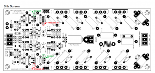
There was an error on the silkscreen for V3.0 board that showed an incorrect pin out of of Q106, This problen was corrected on V3.01 and is documented in Jans Documentation
v3.01
Hi, can you give me link to thiss side, please?
LP Aleš
There was an error on the silkscreen for V3.0 board that showed an incorrect pin out of of Q106, This problen was corrected on V3.01 and is documented in Jans Documentation
Hi, can you give me link to thiss side, please?
LP Aleš
Hi, can you give me link to thiss side, please?
LP Aleš
Hi, there cold be silkscreen error, but the sopper paths on the bottom on top are correct acording silkscreen.
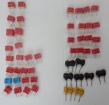
I'm in the beginning of my LYNX project, are still searching parts. I have got the transformer, the chassis and a bunch of capacitors and wonder if they can be useful:
I have 16 pcs 80v 15000mfd Cornell Dubilier Snap-in type.
Rating:
15000uF
80Volts
+ / -20%
Temperature Rating:-40c +85 c
Physical Size: Diameter 35 mm. Height 82 mm.
Anyone have a clue?
I have 16 pcs 80v 15000mfd Cornell Dubilier Snap-in type.
Rating:
15000uF
80Volts
+ / -20%
Temperature Rating:-40c +85 c
Physical Size: Diameter 35 mm. Height 82 mm.
Anyone have a clue?
.....wonder if they can be useful:
I have 16 pcs 80v 15000mfd Cornell Dubilier Snap-in type.
Anyone have a clue?
lucky you 😀
Bought these capacitors a few years ago.
Thought they would not be good enough for the LYNX.😱
Since I am not electronics engineer i think i need some help with the layout for the psu...🙄
Thought they would not be good enough for the LYNX.😱
Since I am not electronics engineer i think i need some help with the layout for the psu...🙄
Your best bet would be a pcb designed for snap in type capacitors. Do a search for
"power supply pcb"
on this forum and you might find what you are looking for.
Good luck.
"power supply pcb"
on this forum and you might find what you are looking for.
Good luck.
very lucky
Your very lucky my friend, you can try destroyer X psu, Mr. Rudi is offering it on the group buy on this link:http://www.diyaudio.com/forums/group-buys/187592-3-symasym-48.html, maybe he have spare.
Regards,
mj777
I'm in the beginning of my LYNX project, are still searching parts. I have got the transformer, the chassis and a bunch of capacitors and wonder if they can be useful:
I have 16 pcs 80v 15000mfd Cornell Dubilier Snap-in type.
Rating:
15000uF
80Volts
+ / -20%
Temperature Rating:-40c +85 c
Physical Size: Diameter 35 mm. Height 82 mm.
Anyone have a clue?
Your very lucky my friend, you can try destroyer X psu, Mr. Rudi is offering it on the group buy on this link:http://www.diyaudio.com/forums/group-buys/187592-3-symasym-48.html, maybe he have spare.
Regards,
mj777
Bought these capacitors a few years ago.
Thought they would not be good enough for the LYNX.😱
Since I am not electronics engineer i think i need some help with the layout for the psu...🙄
I have PSU cards + connectors from peranders group buy from some time ago.
Let me know if you're interested!
/Bosse, Lund.
070-3142354
hai, can i use TL072 in the place of OPA627 in Lynx v3 amplifier with any problems? pls send replay to robinsrakath@gmail.com
- Status
- Not open for further replies.
- Home
- Amplifiers
- Solid State
- Official LYNX Power Amp builder’s thread