I reply your PM. Cross conduction means that upper (lower) device of the class AB amplifier does not source output current only to load, but also to lower (upper) device, that did not succeed in turning off. (Poor drive technique of output devices). This may be quite dangerous situation, because the cross current may rise to very high values and output device SOA may be exceeded, resulting in semiconductor failure. You apparently have problems with stability for sure. In case you want a help, please send me a detailed schematic of the amplifier you have built with all component types and values.
Frankly speaking, I do not like much this amplifier's topology.
Frankly speaking, I do not like much this amplifier's topology.
so I can't even give my boards away for free 😱
btw, wasn't some of the more severe problems around this amp issues coming from fake components
I think it was described
ESP Elliot Sound also had his share of this, issues with fake transistors
and he writes about it too
btw, wasn't some of the more severe problems around this amp issues coming from fake components
I think it was described
ESP Elliot Sound also had his share of this, issues with fake transistors
and he writes about it too
2 Masoudgh
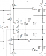
Try to ad 100pF capacitor between pins 6 and 2 at opamp. Also add blocking capacitors 100nF across resistors R107, R107. This should help with stability problems (oscilations around 2MHz).
To solve crossconduction problems , remove conection of R116, R117 to output, connect this resistors to series between bases of Q110, Q111 and bypass it with capacitor about 100nF. Do the same with R118, R119 and add bypass with capacitor 470n-1uF between bases of power devices. This should speed-up turn off in power stage and reduce crosscurrent in output devices.
Attachments
Last edited:
thank you so much dear Pavel.
at first you have to know that my output device is true and not broken.
only Q110 and Q111 and R128 to R135,R117 and R119 became blew.
after this happen two fuses became broken.
I built LYNX amplifier and all of thing is according schematic diagram and component list.
however I changed some of component:
for output device I used TOSHIBA 2SC5200 and 2SA1943.because the recommended transistors not available for me.
for Q104 ,Q105and Q106 I replace KSE340 that it is equal with MJE340.
but for Q103 and Q107 I used A1156 that it is equivalent with MJE350.
Because my MJE350 was poor.
all of them are original and high grade.
for R138 to R145 I used 0.51R high quality resistor.
R118 AND R119 are 33R.
U1 is OPA134.
Rail voltage is -/+55 volt and my transformer is toroidal 610Watts for per channel.
So capacitor bank is 2x22000uf and some 100nf…
for test I used 3A fuse per line of rail voltage.
what value do I have to use for R124 and 125.
I get 150R.
Last edited:
High Ft
2 issues - (with higher Ft outputs)
-10-22r basestoppers on the MJE15032/33's
-Decouple driver/ predriver stage from output stage with 10-22r - 10-22uf/.1uf RC network , both rails.
This will make for a well behaved triple OP , even with VERY high Ft devices. Bob Cordell's new book gives all the details , and .... in real life , it works. 🙂
It seems the Lynx is specifically designed with 4Mhz Ft OP's in mind.
The original Leach amp is the same way and must use MJ's or 21193/4's.
OS
thank's BV.
but right now my amp doesn't have any oscillation and.please read post of no619.
but about cross conduction problems!
I didn't exact understand it.could you please more explain to me.
thank's .
but right now my amp doesn't have any oscillation and.please read post of no619.
but about cross conduction problems!
I didn't exact understand it.could you please more explain to me.
thank's .
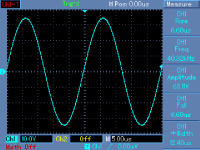
I think there is another problem.what is this in this waveform?is it oscillation as well?
An externally hosted image should be here but it was not working when we last tested it.
yes I know.but how can I get measurement like this ?
do you know what is this in my measurement?
so can you help me about SOA of my amp and other thing?
do you know what is this in my measurement?
so can you help me about SOA of my amp and other thing?
Sorry, I really cannot spend much time posting here, I am pretty busy. I have already instructed you how to provide me necessary information, in case you ask for my help. I am not going through this thread finding what happened and what has not.
You are asking for a help, not me.
You are asking for a help, not me.
which did amplifier measure?
I have read all of thing through this thread.but I didn't find anything about this situation.
I have read all of thing through this thread.but I didn't find anything about this situation.
Last edited:
You were offered a real help, which you refused to follow. The problem is completely on your side. And BV has given an advice to you. Did you try it?
No.I didn't try it.because I afraid that my amp become blew again.
Why doesn't Mr Jan try this modification?
Dear PMA...you ask me about my configuration and I provided to you it.
You wanted to help me about SOA of my amp and so prevent cross conduction.but you say me don't have enough time and are busy.dear PMA,I don't have enough knowledge about this situation and I asked Mr Jan that he was designer of this amp.but after around of two week there is no any answer form him.because of this I discussed my problem in this forum.
now help me about SOA and so tell me do you recommend the advice of dear BV?if you confirm it,I will sure that try it.
So is it any way to percent cross conduction?for instance if I change U1 what will happen?
thank you so much.
Last edited:
Solution
Hi all.
my problem solved...but with many help of Mr Pavel(PMA).
now there is no any oscillation in my amp and this is very stable.before it I couldn't adjust R114 exactly.but now this is stable and I could adjust it, very simple and was exact.
now these are full result of Pavel kindness:
after 100Hz:
before 100Hz:
after 1KHz:
before 1KHz:
after 10KHz:
before 10KHz:
with recommendation of Pavel and after several test ,finally this problem solved by adding a 100pf cap from Collector of Q3(Anode D107) to ground.
for self oscillation I used a 22pf from pin 2 to 6.so I replace a 22pf for C109.becuse this value(100pf) for OPA134 was very high and I had to do this.
it was total of my modification.
thank you so much dear Pavel.
Hi all.
my problem solved...but with many help of Mr Pavel(PMA).
now there is no any oscillation in my amp and this is very stable.before it I couldn't adjust R114 exactly.but now this is stable and I could adjust it, very simple and was exact.
now these are full result of Pavel kindness:
after 100Hz:
An externally hosted image should be here but it was not working when we last tested it.
before 100Hz:
An externally hosted image should be here but it was not working when we last tested it.
after 1KHz:
An externally hosted image should be here but it was not working when we last tested it.
before 1KHz:
An externally hosted image should be here but it was not working when we last tested it.
after 10KHz:
An externally hosted image should be here but it was not working when we last tested it.
before 10KHz:
An externally hosted image should be here but it was not working when we last tested it.
with recommendation of Pavel and after several test ,finally this problem solved by adding a 100pf cap from Collector of Q3(Anode D107) to ground.
for self oscillation I used a 22pf from pin 2 to 6.so I replace a 22pf for C109.becuse this value(100pf) for OPA134 was very high and I had to do this.
it was total of my modification.
thank you so much dear Pavel.
Last edited:
Hi Pavel,
Would you suggest these mods be made to stabilise the amp anyways. I ask because I don't have access to a scope and a total newbie to building amps.
Are there other mods you would suggest to this design. Thanks.
BV,
Could you please help understand what you suggested in post 626, a diagram would be great. Could we do this irrespective of whether there are problems or not ?
sunil
- Status
- Not open for further replies.
- Home
- Amplifiers
- Solid State
- Official LYNX Power Amp builder’s thread