Version 4.0 Lynx
Other than fixing the oscillations issues that are solved above, what would you like to see in a 'version 4.0'?
Other than fixing the oscillations issues that are solved above, what would you like to see in a 'version 4.0'?
... what would you like to see in a 'version 4.0'?
dont know
I reckon this amp was created around the time when OPA627 was really 'hot'
and people tried to 'mod' everything with it 😱
it was almost like nothing else would do
seem like its more or less 'outdated' now 😕
but then, for alternative it might be simpler to consider apexaudio PA amp, or ESP sub amp
Help with recovery
Hello
I'm building lynx v3, and i have problem with recovery. Pre-test result was ok, i adjust potentiometer to 1.4V between "tpA and tpC", offset 30mV, R122/123 a little hot (guess it's normal).
But when i fit Q112-119 and goes to final test, i cannot set quiescent current. I tried to adjust potentiometer to 10mV, but i could not get to close to this value. Voltage between "tpG and tpH" is still 47mV, and when i adjust bias too low it drop to 0mV. Value does not move with the rotation of the potentiometer, just quickly fall.
I fit three equally PCB, and it do same.
Power supply 60VDC. For safety i used 40R 20W resistors to each power +- branch, not to gnd. When i done pre-test, resistors was cool, but when i do final test to set quiescent current, resistors goes hot.
https://picasaweb.google.com/1151950...CJ20qoe5u-20fA
Assembly guide: Schematic and "components list" are not same values, i have worry about it.
Here is my fitted components:
I am a beginner, it's my hobby just two years.
Hello
I'm building lynx v3, and i have problem with recovery. Pre-test result was ok, i adjust potentiometer to 1.4V between "tpA and tpC", offset 30mV, R122/123 a little hot (guess it's normal).
But when i fit Q112-119 and goes to final test, i cannot set quiescent current. I tried to adjust potentiometer to 10mV, but i could not get to close to this value. Voltage between "tpG and tpH" is still 47mV, and when i adjust bias too low it drop to 0mV. Value does not move with the rotation of the potentiometer, just quickly fall.
I fit three equally PCB, and it do same.
Power supply 60VDC. For safety i used 40R 20W resistors to each power +- branch, not to gnd. When i done pre-test, resistors was cool, but when i do final test to set quiescent current, resistors goes hot.
https://picasaweb.google.com/1151950...CJ20qoe5u-20fA
Assembly guide: Schematic and "components list" are not same values, i have worry about it.
Here is my fitted components:
Code:
[FONT=Arial, sans-serif][SIZE=2]R101                               1K           0.6W[/SIZE][/FONT]
[FONT=Arial, sans-serif][SIZE=2]R102                               100K        0.6W[/SIZE][/FONT]  [FONT=Arial, sans-serif][SIZE=2]
R103, 104, 107, 108         1K            0.6W[/SIZE][/FONT]
[FONT=Arial, sans-serif][SIZE=2]R105, 106                        13K          0.6W[/SIZE][/FONT]  [FONT=Arial, sans-serif][SIZE=2]
R109, 110                         3.3K        0.6W[/SIZE][/FONT]  [FONT=Arial, sans-serif][SIZE=2]
R111, 112                         330R        2W[/SIZE][/FONT]  [FONT=Arial, sans-serif][SIZE=2]
R113                                1K8          0.6W[/SIZE][/FONT]
[FONT=Arial, sans-serif][SIZE=2]R115                                200R        0.6W[/SIZE][/FONT]  [FONT=Arial, sans-serif][SIZE=2]
R116, 117                         180R        0.6W [/SIZE][/FONT]   [FONT=Arial, sans-serif][SIZE=2]
R118, 119                         33R          2W[/SIZE][/FONT]
[FONT=Arial, sans-serif][SIZE=2]R120                                10K          0.6W[/SIZE][/FONT]  [FONT=Arial, sans-serif][SIZE=2]
R121                                390R        0.6W [/SIZE][/FONT]   [B][FONT=Arial, sans-serif][SIZE=2]
R122, 123                         2k2          2W[/SIZE][/FONT][/B]  [B][FONT=Arial, sans-serif][SIZE=2]
R124, 125                         24R          0.6W[/SIZE][/FONT][/B]  [FONT=Arial, sans-serif][SIZE=2]
R126, 127                         100R        0.6W[/SIZE][/FONT]  [B][FONT=Arial, sans-serif][SIZE=2]
R128 to 135                      0R22        5W[/SIZE][/FONT][/B]  [FONT=Arial, sans-serif][SIZE=2]
R136, 137                         10R          5W[/SIZE][/FONT]
[FONT=Arial, sans-serif][SIZE=2]R138 to 145                      4R7          0.6W[/SIZE][/FONT]
   [FONT=Arial, sans-serif][SIZE=2]
R114                                 2K        250mW[/SIZE][/FONT]

[FONT=Arial, sans-serif][SIZE=2]C101                                              330pF       100VDC[/SIZE][/FONT]
[FONT=Arial, sans-serif][SIZE=2]C102, 103                                       33pF        100VDC[/SIZE][/FONT]
[FONT=Arial, sans-serif][SIZE=2]C105, 106                                       22uF        50V, bipolar[/SIZE][/FONT]  [FONT=Arial, sans-serif][SIZE=2]
C104, 107, 108, 112, 113,114, 115     100nF      100VDC[/SIZE][/FONT]
[FONT=Arial, sans-serif][SIZE=2]C109                                              100pF       100VDC[/SIZE][/FONT]  [FONT=Arial, sans-serif][SIZE=2]
C110                                               470uF      16V, polar[/SIZE][/FONT]
[FONT=Arial, sans-serif][SIZE=2]C111                                               100nF       400VDC[/SIZE][/FONT]     [FONT=Arial, sans-serif][SIZE=2]

U101                             OPA627AP[/SIZE][/FONT]

[FONT=Arial, sans-serif][SIZE=2]Q101, 108                      MPSA42G[/SIZE][/FONT]  [FONT=Arial, sans-serif][SIZE=2]
Q102, 109                      MPSA92G[/SIZE][/FONT]
[FONT=Arial, sans-serif][SIZE=2]Q103, 107                      MJE350[/SIZE][/FONT]  [FONT=Arial, sans-serif][SIZE=2]
Q104, 105, 106               MJE340[/SIZE][/FONT]
[FONT=Arial, sans-serif][SIZE=2]Q110                              MJE15032G[/SIZE][/FONT]
[FONT=Arial, sans-serif][SIZE=2]Q111                              MJE15033G[/SIZE][/FONT]  [FONT=Arial, sans-serif][SIZE=2]
Q112, 114, 116, 118         MJL21194G[/SIZE][/FONT]
[FONT=Arial, sans-serif][SIZE=2]Q113, 115, 117, 119         MJL21193G[/SIZE][/FONT]    [FONT=Arial, sans-serif][SIZE=2]

D101 to 106                  1N4148[/SIZE][/FONT]  [FONT=Arial, sans-serif][SIZE=2]
D107, 108                      BAV21[/SIZE][/FONT]
[FONT=Arial, sans-serif][SIZE=2]ZD101, ZD102                15V Zener    1W
[/SIZE][/FONT]Seems as if there are many issues with the LYNX amp, did anyone get theamp working properly? Or is the latest revision stable?
Im thinking of taking on this project.
Thanks
Im thinking of taking on this project.
Thanks
http://www.diyaudio.com/forums/soli...ower-amp-builder-s-thread-33.html#post1708821
Baby Lynx - Power Amplifier | Electronic Projects
It is the Baby Lynx, but dont found the schematic
Baby Lynx - Power Amplifier | Electronic Projects
It is the Baby Lynx, but dont found the schematic
http://www.diyaudio.com/forums/soli...ower-amp-builder-s-thread-33.html#post1708821
Baby Lynx - Power Amplifier | Electronic Projects
It is the Baby Lynx, but dont found the schematic
Try this:
DIY HiFi Audio Pages: Zesilovaèe
Hello all.
I have made this amp and is ready to test.
To be honest,I'm afraid to connect the rail voltage directly.because this is +/-60V-700VA.
Actually I was success in pre-test and I could adjust the voltage of tp-A and tp-C to 1.4V easily.
After pre test,I installed the Q112 to Q119.
I have a -/+55 volts-3A Digital power supply.I connected that to my amp.I adjust the voltage at Maximum but limited the current at 1.5A.but the voltage did not come to more than +/-18V evan at maximum current(3A) .
The Digital power supply could not drive the amp. therefore I used the main toroidal transformer for final test(2X42V AC-700VA).
As I said before ,I was afraid to connect that directly.
Therefore I paralleled two 10R(50W) with main rail voltage to limit the current.But the resistors got very warm and the voltage did not come to more than -/+ 20V.
Even I adjusted the R114 but was not effective.
It seems there is a problem,because the circuit need Irrational current,but I don’t know for which part.
Because I was success in pre test.
I have chosen 0.39R for R128 to R135.
So I chose 100R for R124 and125 according to rail voltage and R128 to R135 amount.please confirm if I was true.
I need your help to solve the problem.
Thanks...
The problem is related to OPA134.
I replaced TL071 instead of OPA134 and I could adjust R114.
But I what to use OPA134 because of its quality and lower distortion.
I removed C109 and the problem has been solved for OPA134 and I could adjust R114.
But I don’t know this is true work and so I don’t know its effect in the circuit.
Help please.
Can you set the output stage bias current to zero?
Then do that.
Power up the amplifier via a mains bulb tester.
Measure the supply rail voltages.
Measure the Vbias at the multiplier.
Measure the input stage voltages.
Measure the VAS stage voltages.
Measure the driver stage voltages.
If all of these are as expected, then start to adjust the Vbias while you measure the Vbias voltage. Does the Vbias change with adjustment of the VR?
If not as expected, then write the measured voltages on the schematic and post a pic here.
or
Power down.
Connect without the bulb tester.
Power up.
Set the Vbias using VR.
Thanks to reply dear my friend.
I could not to set zero for OPA134.
I have made several change in below process:
1-I changed C109 value to 22pf instead of 100pf
2-I have put a 22pf between pin6 and 2 of OPA134.
3-I connected collector of Q103 and Q104 to GND via 22pf capacitor.
know the amp is completely stable and I could adjust R114 very easy.
I applied 100mv/1khz signal and observed with oscilloscope.
I rose the frequency till 400Khz and I did not see any crossover distortion or oscillation.
So I rose the input signal power to 1,34v and amp clipped.
Everything is ok and very stable.
Please confirm if my changed is right and don’t make problem for other parts.
Hello folks ,
I have a question for those who built this amp :
what is the value of R101 , is it 1 K or 20 K , I saw both values
on several schematics ...
Best regards ,
@ + Philippe.
I have a question for those who built this amp :
what is the value of R101 , is it 1 K or 20 K , I saw both values
on several schematics ...
Best regards ,
@ + Philippe.
After six years on the shelf, I finally found some time to do some more work on this project.
I started out with preparing the heatsinks. I drilled all of the holes on the milling machine for accuracy and followed each hole with a thread forming tap. Rather than cutting the threads, I favour thread forming for small diameter holes in aluminium. These are all M3 holes some of which will need some decent torque on them, so they are at least 20mm deep.


The next thing to do was to develop a jig for bending the leads on the output transistors accurately and consistently.
Using a scrap piece of 25.4mm square aluminium I cut a pocket out to accommodate the body of the transistor with a step at the end at the correct length for the bend. The height of the step also needs to be sufficient to support the leads at the base of the package as they are bent over.

With the transistor mounted face down onto the jig, all that's needed is to tap the protruding leads with a soft rubber mallet to bend them over the edge to form a lovely consistent 90º bend for each lead of each transistor.


Now, with all of the devices mounted, all the holes appear (as if by magic) to align properly with the holes that I drilled in the heatsink.

With that done, we can start to get on with some testing. I set up a bunch of multimeters, an oscilloscope and a signal generator in order to perform the initial configuration, setup and testing.
I have configured this circuit to operate from a ±50V supply, however, my bench supply only goes up to ±30V. This will be OK for what I need to do today until I build the proper power supplies. Also, the bench supply has current limiting which can prove handy in case this amplifier decides to enter into some sort of vicious oscillation mode.
My cautiousness was well founded, actually, because the very first thing this amplifier did was to oscillate horribly at around 2.8MHz with a very expensive OPA627 no less. A TL071 did not exhibit any oscillations and a NE5532 caused oscillations at around 1.3MHz.
Following the advise of other members who have contributed to this thread especially Stephan sch, I replaced C109 with a 22pF capacitor, soldered 22pF capacitors from the collectors of Q103 and Q104 to GND. Reluctantly I also had to solder another 22pF capacitor over pins 2 and 6 of the lovely OPA627.
Various leads and probes hooked up to perform tests of the VAS. Don't worry about the test clips across one of the emitter resistors, look upper left, the wires destined for the CAS are flapping about in the breeze.

With the modifications, the VAS stopped oscillating and the bias voltage could be set easily.
Now it's time to connect up the CAS along with a 6.8Ω resistive load on the output.

I got some of my multimeters out so that I could monitor various aspects of the setup simultaneously.
From left to right, the Fluke 287 is just sitting in standby with the leads ready to take random measurements at will. The Fluke 89 is measuring the bias voltage across TPA and TPC. The Gossen is measuring the quiescent current through one of the drivers. Finally, the Fluke 25 is measuring the AC line voltage. Here I have set it to 230VAC. My workspace is purely solar powered, so when I perform high power tests such as these, I like to keep an eye on how the inverter is performing. It's a high quality Victron 2KVA inverter, so there is no reason to doubt it's performance, I am just interested in looking at these sort of things.
Interestingly, the Solartron bench multimeter in the background was initially measuring the quiescent current over the emitter resistors but it caused oscillations, so the battery powered Gossen was employed for the task at which point the oscillations went away.

Here is a helicopter view of the whole lash up.

Now we can actually take a look at the performance of this thing. After the modifications, I am reasonably impressed. The only thing I am not so happy about is having to slow down a very expensive Op-Amp. Having said that, in my case, the rise time is still quicker with the modified OPA627 than with the respectable NE5532 (which also needs a 22pF across it).
So, with the DC bias and quiescent current set correctly, let's get on with some AC measurements.
I should note that I am not overly fanatical about a DC coupled front end such as this design, so the eagle eye'd may have noticed a great big 4.7uF capacitor which provides AC coupling between the amplifier and my signal generator.
In all of the below screen shots from my oscilloscope, the green trace is the input signal, the yellow is the output signal.
Here is a 1KHz square wave with a 1V P-P input. The amplifier has some slight ringing but nothing to worry about. The specified (sine wave) gain of 25 at this stage has been superseded. Although I suspect that the oscilloscope is measuring the peaks of the ringing, it looks good to me.
What I am looking out for in particular with a square wave input is the rise time. Here we can see a rise time of 740nS which roughly suggests a bandwidth of 500KHz. This, to me, is an acceptable sort of bandwidth to expect from an audio amplifier.
The bandwidth of my generator is 20MHz, so expect it's representation of a 1KHz square wave signal to be pretty faithful.

Here is the sine wave. Here we have a gain of 25.05, what more can you expect?

How far can the input signal go? Let's investigate. Once agin, with a square wave, I wound up the wick from the signal generator. The negative half of the output signal starts oscillating with an input voltage of about 1.9V P-P. At nearly twice the regular input voltage, I am not one to complain.

Back down to 1V P-P, let's zoom into that ringing a bit........

.....and a bit more.

In order to get a better view of the ringing, let's wind up the input frequency to 100KHz. Note, the rise time is what we are interested in from a bandwidth point of view, this is still 740nS. We are winding up the input frequency in order to get a closer look at the ringing. The generator is still producing a reasonably faithful signal.

At 100KHz, sine looks good too. Gain has dropped to 24.7, who's complaining, we are way out of the design bandwidth.

Let's double the input frequency, 200KHz. The gain is now down to 23.5, wow, not bad. Although you can now see some distortion at the peaks.

So, that was fun. Let's look at the band that matters, the audio one.
Sine at 10KHz, input 1V P-P:

Square at 10KHz, input 1V P-P:

Sine at 20KHz, input 1V P-P:

Square at 20KHz, input 1V P-P:

Goodness knows how Jan managed to get acceptable performance from his original design. I could only achieve the performance that I have demonstrated with the modifications that have been suggested by other members who have contributed to this thread, thank you.
I started out with preparing the heatsinks. I drilled all of the holes on the milling machine for accuracy and followed each hole with a thread forming tap. Rather than cutting the threads, I favour thread forming for small diameter holes in aluminium. These are all M3 holes some of which will need some decent torque on them, so they are at least 20mm deep.
The next thing to do was to develop a jig for bending the leads on the output transistors accurately and consistently.
Using a scrap piece of 25.4mm square aluminium I cut a pocket out to accommodate the body of the transistor with a step at the end at the correct length for the bend. The height of the step also needs to be sufficient to support the leads at the base of the package as they are bent over.
With the transistor mounted face down onto the jig, all that's needed is to tap the protruding leads with a soft rubber mallet to bend them over the edge to form a lovely consistent 90º bend for each lead of each transistor.
Now, with all of the devices mounted, all the holes appear (as if by magic) to align properly with the holes that I drilled in the heatsink.
With that done, we can start to get on with some testing. I set up a bunch of multimeters, an oscilloscope and a signal generator in order to perform the initial configuration, setup and testing.
I have configured this circuit to operate from a ±50V supply, however, my bench supply only goes up to ±30V. This will be OK for what I need to do today until I build the proper power supplies. Also, the bench supply has current limiting which can prove handy in case this amplifier decides to enter into some sort of vicious oscillation mode.
My cautiousness was well founded, actually, because the very first thing this amplifier did was to oscillate horribly at around 2.8MHz with a very expensive OPA627 no less. A TL071 did not exhibit any oscillations and a NE5532 caused oscillations at around 1.3MHz.
Following the advise of other members who have contributed to this thread especially Stephan sch, I replaced C109 with a 22pF capacitor, soldered 22pF capacitors from the collectors of Q103 and Q104 to GND. Reluctantly I also had to solder another 22pF capacitor over pins 2 and 6 of the lovely OPA627.
Various leads and probes hooked up to perform tests of the VAS. Don't worry about the test clips across one of the emitter resistors, look upper left, the wires destined for the CAS are flapping about in the breeze.
With the modifications, the VAS stopped oscillating and the bias voltage could be set easily.
Now it's time to connect up the CAS along with a 6.8Ω resistive load on the output.
I got some of my multimeters out so that I could monitor various aspects of the setup simultaneously.
From left to right, the Fluke 287 is just sitting in standby with the leads ready to take random measurements at will. The Fluke 89 is measuring the bias voltage across TPA and TPC. The Gossen is measuring the quiescent current through one of the drivers. Finally, the Fluke 25 is measuring the AC line voltage. Here I have set it to 230VAC. My workspace is purely solar powered, so when I perform high power tests such as these, I like to keep an eye on how the inverter is performing. It's a high quality Victron 2KVA inverter, so there is no reason to doubt it's performance, I am just interested in looking at these sort of things.
Interestingly, the Solartron bench multimeter in the background was initially measuring the quiescent current over the emitter resistors but it caused oscillations, so the battery powered Gossen was employed for the task at which point the oscillations went away.
Here is a helicopter view of the whole lash up.
Now we can actually take a look at the performance of this thing. After the modifications, I am reasonably impressed. The only thing I am not so happy about is having to slow down a very expensive Op-Amp. Having said that, in my case, the rise time is still quicker with the modified OPA627 than with the respectable NE5532 (which also needs a 22pF across it).
So, with the DC bias and quiescent current set correctly, let's get on with some AC measurements.
I should note that I am not overly fanatical about a DC coupled front end such as this design, so the eagle eye'd may have noticed a great big 4.7uF capacitor which provides AC coupling between the amplifier and my signal generator.
In all of the below screen shots from my oscilloscope, the green trace is the input signal, the yellow is the output signal.
Here is a 1KHz square wave with a 1V P-P input. The amplifier has some slight ringing but nothing to worry about. The specified (sine wave) gain of 25 at this stage has been superseded. Although I suspect that the oscilloscope is measuring the peaks of the ringing, it looks good to me.
What I am looking out for in particular with a square wave input is the rise time. Here we can see a rise time of 740nS which roughly suggests a bandwidth of 500KHz. This, to me, is an acceptable sort of bandwidth to expect from an audio amplifier.
The bandwidth of my generator is 20MHz, so expect it's representation of a 1KHz square wave signal to be pretty faithful.
Here is the sine wave. Here we have a gain of 25.05, what more can you expect?
How far can the input signal go? Let's investigate. Once agin, with a square wave, I wound up the wick from the signal generator. The negative half of the output signal starts oscillating with an input voltage of about 1.9V P-P. At nearly twice the regular input voltage, I am not one to complain.
Back down to 1V P-P, let's zoom into that ringing a bit........
.....and a bit more.
In order to get a better view of the ringing, let's wind up the input frequency to 100KHz. Note, the rise time is what we are interested in from a bandwidth point of view, this is still 740nS. We are winding up the input frequency in order to get a closer look at the ringing. The generator is still producing a reasonably faithful signal.
At 100KHz, sine looks good too. Gain has dropped to 24.7, who's complaining, we are way out of the design bandwidth.
Let's double the input frequency, 200KHz. The gain is now down to 23.5, wow, not bad. Although you can now see some distortion at the peaks.
So, that was fun. Let's look at the band that matters, the audio one.
Sine at 10KHz, input 1V P-P:
Square at 10KHz, input 1V P-P:
Sine at 20KHz, input 1V P-P:
Square at 20KHz, input 1V P-P:
Goodness knows how Jan managed to get acceptable performance from his original design. I could only achieve the performance that I have demonstrated with the modifications that have been suggested by other members who have contributed to this thread, thank you.
I am having the same problem with three different versions of a Symasym.
Damped ripple still exists after I have added various "slowing down" compensations.
As I increase the signal the ringing appears less in proportion to the whole signal.
As I decrease the input signal, my lowest is 46mVac giving ~2Vac at the output, the ringing looks worst.
Without the added, or increased compensations, two of the Symasyms went into complete oscillation (even with 1kHz sinewave.) with tiny output capacitance one @ 4n7F and the other @ 10nF.
I can reduce the ringing, I cannot get rid of it. I am lost.
What does your output look like when you reduce the input?
Is your ringing evident with resistor loading only or is that R||C loading?
What if you remove the R and test with just C loading?
Last edited:
Hello folks ,
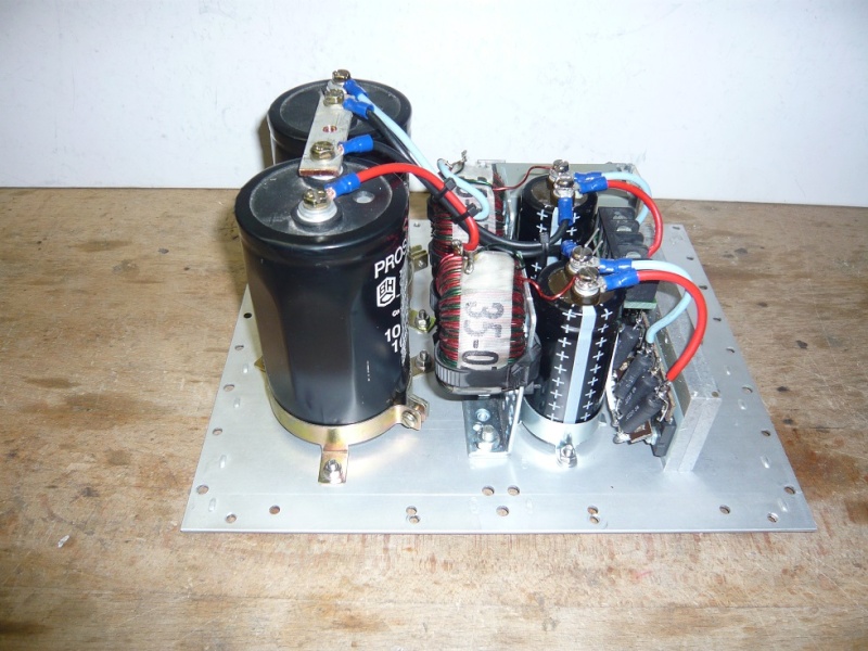
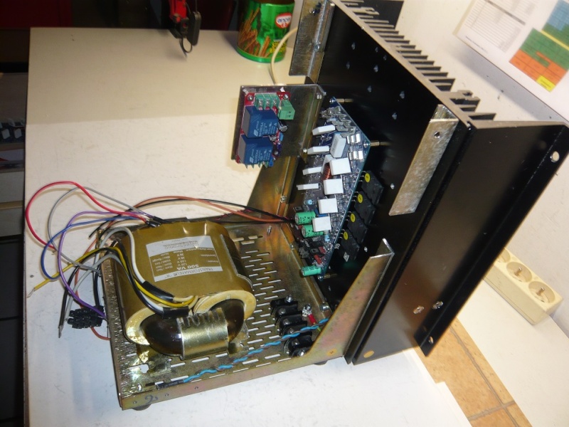
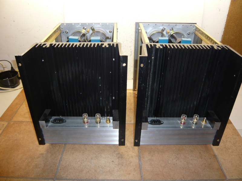
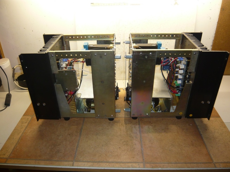
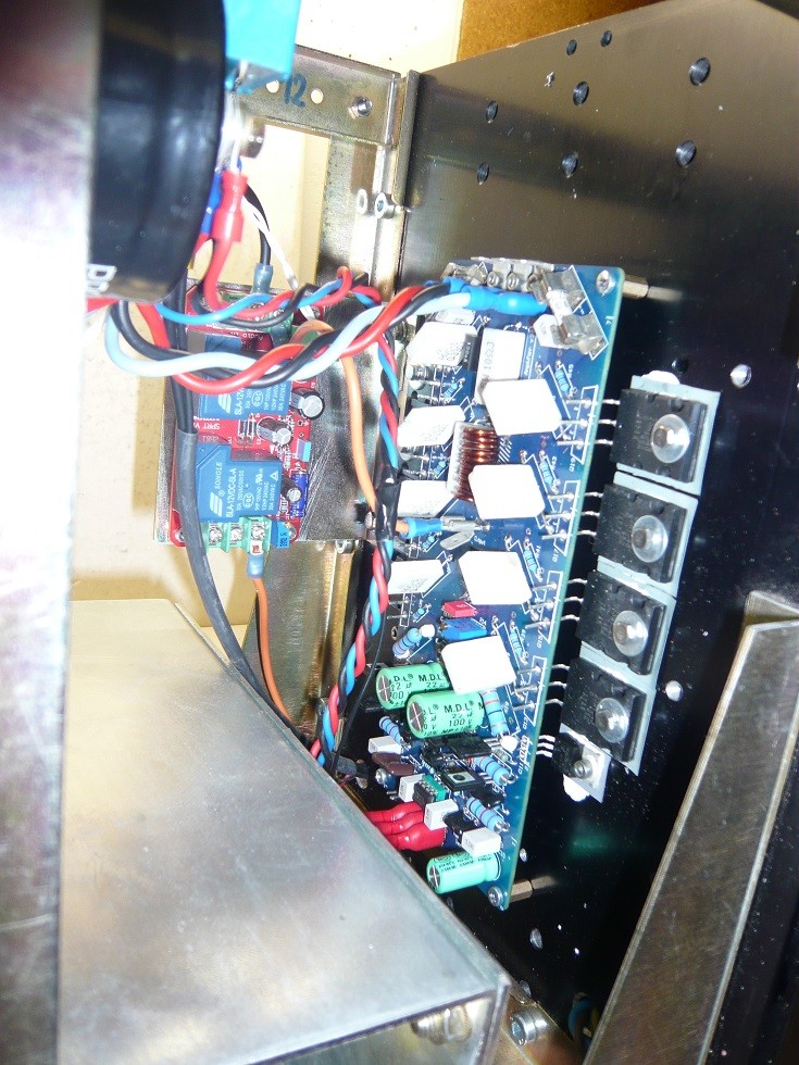
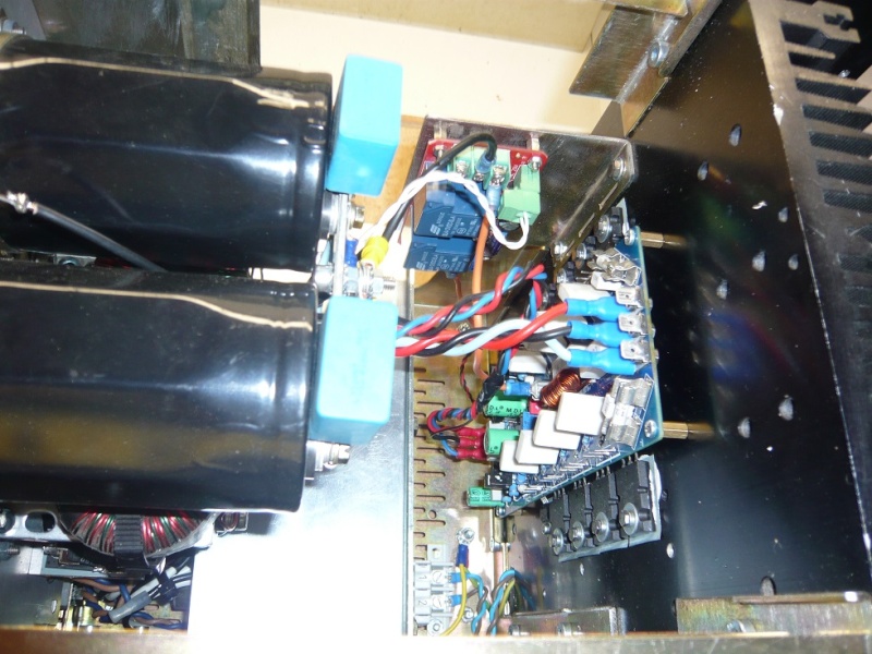
here is my contribution , ( at least ! )
I built 2 MONOblocks oh this amp , as you can see on the following pictures:
 [/url]
 [/url]
 [/url]
 [/url]
 [/url]
 [/url]
 [/url]
Sounds very nice !
@ + Philippe .
here is my contribution , ( at least ! )
I built 2 MONOblocks oh this amp , as you can see on the following pictures:
Sounds very nice !
@ + Philippe .
- Status
- Not open for further replies.
- Home
- Amplifiers
- Solid State
- Official LYNX Power Amp builder’s thread