I have only "changed" C102 & C103 to SILVER MICA 33 PF, and Q103 to Q107 are ST Microelectronics (not OnSemi).
All parts are purchased at a well known (In Denmark) electronic supplier.
Today I did some more tests: After about 10min the tp A to tp B is stable – and can be adjusted to 1.4V without any problems. Tp B to GND is going from 32mA at power up to 55mA after approx. 10min.
My powersupply is only “preliminary” with one diode bridge, 2 x 10000uF with 100nF in parallel - can this cause the problems?
Fix the other PCB:
Also here Q110 & Q111 = dead - and R138, R140, R142, R144 = dead.
Changed Q110 & Q111 and are running pre-test at 1.4V tp A > tp C and tp B > GND = 5mA slowly incressing to 27mA after 10min.
I do really not like to connect the power transistors

Also here Q110 & Q111 = dead - and R138, R140, R142, R144 = dead.
Changed Q110 & Q111 and are running pre-test at 1.4V tp A > tp C and tp B > GND = 5mA slowly incressing to 27mA after 10min.
I do really not like to connect the power transistors
Hello All,
Sorry for this late respons to this thread, but my ordinary work has been killing me the last month
I have just done some further testing, and had to pull three LYNX pcbs out and onto my workbench before I found one that did oscillate when the OPA134 was inserted (as many of you may know I prefer the old LF356 for this amp my self).
These are the measurements that I came up with.
LF356 - No oscillation
Pre-test:
DC-Offset: +0.2mV
tp A to tp C: 1.401V
tp A to Gnd: +706mV
tp C to Gnd: -701mV
I did manage to provoke some oscillation using long unbraided wires. Cure: A 22pF cap from pin 2 to pin 6.
Final test. No oscillation
OPA134 - one PCB with oscillation app. 5Vp-p at app. 2 MHz
Pre-test:
DC-Offset: +0.2mV
tp A to tp C: 1.394V
tp A to Gnd: +701mV
tp C to Gnd: -698mV
Oscillated even when using very short braided wires.
Again I tried a 22 pF cap from pin 2 to pin 6. Still some oscillation.
Went to final test (with the OPA134 still oscillating) and placed another 100nF cap across Output Stage +DC to Gnd and -DC to Gnd. No oscillation at all to be seen with scope Volts/Div. set to 5mV x5mag.
I hope this will help some of those having problems.
Thanks for your patience 🙂
That's really great reading, Jan!
So, from your post I take it there is a possibility for oscillations with the output stage not connected, and they could dissappear when connecting the output stage?
I'm still struggling with getting the LM49170 to work. I can't wait to try your fix. My oscillations didn't go away whatever cap I used between pin2-pin6. Perhaps your fix of adding more decoupling on the output stage will help me as well?
As of now, my amp behaves a bit strange. I start it up and everything is fine, but as soon as a signal is introduced there is a loud buzzing noise, even though I have a new layout with all of Andrews tips about ground wires. Could be an oscillation, even with my fake OPA627's.
Here are two pictures of the latest layout:
Best regards,
/Bo
So, from your post I take it there is a possibility for oscillations with the output stage not connected, and they could dissappear when connecting the output stage?
I'm still struggling with getting the LM49170 to work. I can't wait to try your fix. My oscillations didn't go away whatever cap I used between pin2-pin6. Perhaps your fix of adding more decoupling on the output stage will help me as well?
As of now, my amp behaves a bit strange. I start it up and everything is fine, but as soon as a signal is introduced there is a loud buzzing noise, even though I have a new layout with all of Andrews tips about ground wires. Could be an oscillation, even with my fake OPA627's.
Here are two pictures of the latest layout:
An externally hosted image should be here but it was not working when we last tested it.
An externally hosted image should be here but it was not working when we last tested it.
Best regards,
/Bo
Thanks Jan.
Another cap, you mean one more in parallel, or one 200nF ?
Bo, it´s certainley not good having the cables laying upon the transformer in that way.
Just a tip.
Lose the cableplint and turn transformer, swirl it 180 degrees, so you have the sek. at the capside.
Assemble the plint on its own stand, between transf. and caps.
Then you can make the cables radically shorter, and away of the transformers worst field.
I'm afraid I'm facing new oscillation problems.
I rebuilt the amp again, removing the hedgehog-socket placed upon the transformer, rotated the transformer 180 degrees and shortened the cables to the rectifiers. The transformer is still in "center tapped" connection.
As I start the amp up and feed it with a square signal, the output looks like this (this is without load):
One or two minutes later, the superimposed oscillations are gone, but the square wave has a small shark fin (picture taken after 10 minutes):
As I start playing some music, It sounds good until I reach a certain volume. At that point, a 620kHz oscillation is introduced and I can't get rid of it unless I detach one of the rca inputs:
This is with one of the phony OPA627:s i purchased, which worked fine before I started rebuilding the amp.
Any clues on this "volume dependant" oscillation? The bias current is 8-10 mV across output emitter resistances. The opamp has 22 pF across pin2 to pin6.
Best regards,
/Bo
I rebuilt the amp again, removing the hedgehog-socket placed upon the transformer, rotated the transformer 180 degrees and shortened the cables to the rectifiers. The transformer is still in "center tapped" connection.
As I start the amp up and feed it with a square signal, the output looks like this (this is without load):
An externally hosted image should be here but it was not working when we last tested it.
One or two minutes later, the superimposed oscillations are gone, but the square wave has a small shark fin (picture taken after 10 minutes):
An externally hosted image should be here but it was not working when we last tested it.
As I start playing some music, It sounds good until I reach a certain volume. At that point, a 620kHz oscillation is introduced and I can't get rid of it unless I detach one of the rca inputs:
An externally hosted image should be here but it was not working when we last tested it.
This is with one of the phony OPA627:s i purchased, which worked fine before I started rebuilding the amp.
Any clues on this "volume dependant" oscillation? The bias current is 8-10 mV across output emitter resistances. The opamp has 22 pF across pin2 to pin6.
Best regards,
/Bo
Bo, i´m afraid you have to start your own thread about different OP-amps and how they are topology dependet.
Then you have absolutely a better chance to get more inputs.
Jan said in his first post:
"I would like to point out that my time is limited and that I have NO possibility nor intend to answer questions like “How will the LYNX Amp sound with xx transistors in the VAS” or “Can I use xx Opamp instead?”
Go for OPA134 from ELFA and make the changes Jan already has described.
If then everything is alright, you can go on with your experiments.
I would not be that strict. The Lynx topology is EXTREMELY sensitive to the opamp used. So, everyone should use the opamp that Jan HAS ALREADY tested and guaranteed as stable. If not, the oscillations must be expected, especially with faster opamps and opamps with lower stability margin.
P.S.: the problems that Bo is adressing are very, very important, and can lead to better understanding of non-linear circuits behaviour, behind the knowledge of an average DIYer.
P.S.: the problems that Bo is adressing are very, very important, and can lead to better understanding of non-linear circuits behaviour, behind the knowledge of an average DIYer.
Ragnwald, PMA and others 😉
Thanks for participating in this thread.
Perhaps a refresh on what I wrote in post 441;
Thanks for participating in this thread.
Perhaps a refresh on what I wrote in post 441;
All;
As I have stated many times in emails and on internet forums, the LYNX was from the very beginning ment as a "replacement" Amp for the good old 70-80s very dynamic Studio Power Amps.
Quite a lot have over the years asked for the LYNX to have "supernatural" specs like BW up to 1 MHz etc., which I always has dissuaded. Please tread the design for what it is; A replacement clone for the 30-40 years old Amps.
The original LYNX was from the very beginning fitted with the LF356 opamp, which works great in this design. This opamp is a bit slow and noisy for todays standard, but it was the standard opamp many years back.......
Over the past years, many have build the LYNX (either using original or home made PCBs) with succes, even though I never thought that the LYNX would be so popular in the DIY world as it has become.
Also the LYNX may be quite a big mouthful for some first time diy'ers due to the high power involved.
And last. Thanks to all who participate in this thread, as it is impossible for me to get time to reply to every question asked
I'm sorry to keep the opamp discussion going here, but there is one thing that is bugging me.
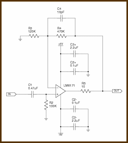
In non-inverting designs, there is a natural cause for placing a local bandwith limiting cap between pin2 and pin6. The insignal is applied to the positive input and feeback goes to the negative pin, as seen here, with C4 acting as the bandwith limiter:
or here:
But, the LYNX uses inverting opamp layout. Wouldn't this mean that to introduce a local bandwidth limiter, the cap must be placed between the output and the positive input, ie, pin3 and pin6?
I'm really trying to get some knowledge of this problem, but not many diy amplifiers are built around inverting input stage.
Best regards,
/Bo
In non-inverting designs, there is a natural cause for placing a local bandwith limiting cap between pin2 and pin6. The insignal is applied to the positive input and feeback goes to the negative pin, as seen here, with C4 acting as the bandwith limiter:
or here:
An externally hosted image should be here but it was not working when we last tested it.
But, the LYNX uses inverting opamp layout. Wouldn't this mean that to introduce a local bandwidth limiter, the cap must be placed between the output and the positive input, ie, pin3 and pin6?
I'm really trying to get some knowledge of this problem, but not many diy amplifiers are built around inverting input stage.
Best regards,
/Bo
masteramp has made a fantastic job with his Baby LYNX;
http://hifi.czweb.org/zesil/lynx.php
Congratulation masteramp 😉
http://hifi.czweb.org/zesil/lynx.php
Congratulation masteramp 😉
Masteramp's baby Lynx does look nice. It would be nice to have a full description of it in English.🙂
jerryo said:Masteramp's baby Lynx does look nice. It would be nice to have a full description of it in English.🙂
The main parts looks same as Jan's big Lynx Amplifier, but have another types of components and some alternations. I'm not so strong in english and the translation to english will take me much time.
Baby uses one pair of 2SC5200/2SA1943 output devices supplied by 40 V. The values of used resistors etc. are adapted for using with 40 V DC power supply and 2SC/2SA. Dual layer PCB consists of top layer with power grounding and bottom layer with supply and signal wires and signal grounding. Power and signal grounding are joined with 10R resistor (Czech way). Is attended to fair ?blocking? (100nF capacitors around OPA, inside the circuit and after the supply connectors).
Here is the link to translate the pages of the Baby Lynx
http://translate.google.com/transla...rg/zesil/lynx.php&sl=cs&tl=en&history_state0=
http://translate.google.com/transla...rg/zesil/lynx.php&sl=cs&tl=en&history_state0=
Rob_S said:Here is the link to translate the pages of the Baby Lynx
http://translate.google.com/transla...rg/zesil/lynx.php&sl=cs&tl=en&history_state0=
This translation is chaotic and incorrect... but maybee is it sufficient. The maximal price of PCB is 15$ (depend on a number of pieces for manufacturing), but I offer the PCB only for Czech (maybee Slovak) Diyers...
Another pcb
hello to everyone ....
been trying to e mail Jan but he is probably on vocation ....
seen the lynx many times before but never took a close look at it it till now
what i realy like about this amp regarding the design since i never listen to it is :
---- symmetric design
---- triple darligton topology
---- Vi limmiters
---- well guarded at every stage of the drivers
---- op amp driven
---- relatively easy to make
now the problems i face is 2
----one is the size of the pcb
---- second is the rail voltage ( it would be perfect for me if rails was max 70 volts or even better 80 )
so i designed a single sided pcb that fits my size and needs hopefully i didnt make any mistakes , in between i had pre drivers located in a way that can be fited on one small heatsink and then added one more pair of transistor outputs .
also kept zobel + inductor away from the pcb since i like it located in the output with separate return to ground
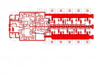
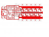
so ...till Jan gets back and share his opinion about higher rails here is a picture of the pcb
kind regards sakis
hello to everyone ....
been trying to e mail Jan but he is probably on vocation ....
seen the lynx many times before but never took a close look at it it till now
what i realy like about this amp regarding the design since i never listen to it is :
---- symmetric design
---- triple darligton topology
---- Vi limmiters
---- well guarded at every stage of the drivers
---- op amp driven
---- relatively easy to make
now the problems i face is 2
----one is the size of the pcb
---- second is the rail voltage ( it would be perfect for me if rails was max 70 volts or even better 80 )
so i designed a single sided pcb that fits my size and needs hopefully i didnt make any mistakes , in between i had pre drivers located in a way that can be fited on one small heatsink and then added one more pair of transistor outputs .
also kept zobel + inductor away from the pcb since i like it located in the output with separate return to ground
so ...till Jan gets back and share his opinion about higher rails here is a picture of the pcb
kind regards sakis
Attachments
Last edited:
- Status
- Not open for further replies.
- Home
- Amplifiers
- Solid State
- Official LYNX Power Amp builder’s thread