the 165Vac across the primary and 31Vac from the secondaries gives the turns ratio. I'll guess this is a 230:40+40Vac transformer.
With the transformer feeding open circuit it should consume just mA of current.
The bulb should appear off if the transformer is good.
With the transformer feeding open circuit it should consume just mA of current.
The bulb should appear off if the transformer is good.
An update on the bulb stuff. When measuring the open circuit current on the transformer, the multimeter says 0A, which means it's in the mA-range. My 60W bulb consumes 0,26A when fully lit, so I guess the bulb itself is not a sharp indication enough. It will ALWAYS be a bit lit.
I'm quite confident my transformer is OK, and I will update the softstart delay and startup current to charge the capacitors faster.
To be nice on the caps, I understand I should have some resistors in parallel to discharge them when the amp is turned off. What would be a good value/wattage of those resistors? I have 60V on the caps.
Also, in my quest to get the LM49170 working, I need to purchase some really small capacitors, in the 10pF to 150pF range. What capacitor type is best for tuning an opamp? All I can find on the elfa.se homepage in these small sizes are ceramic ones. Will they do?
Best regards,
/Bo
no, it should not even glow dimmly when the secondaries are open circuit.bomellberg said:When measuring the open circuit current on the transformer, the multimeter says 0A, which means it's in the mA-range. My 60W bulb consumes 0,26A when fully lit, so I guess the bulb itself is not a sharp indication enough. It will ALWAYS be a bit lit.
/Bo
The tungsten filament bulb passes 260mA from 220Vac when hot.
That's a resistance of ~846r.
The power delivered is ~57W (60W bulb).
The cold resistance will be ~two to three times less than the hot resistance i.e. somewhere between 200r and 400r. Check this cold resistance with your DMM.
Now pass 10mA through that 300r and the power delivered will be ~30mW. The filament will warm slightly. It will not light up!
bomellberg said:
I need to purchase some really small capacitors, in the 10pF to 150pF range. What capacitor type is best for tuning an opamp? All I can find on the elfa.se homepage in these small sizes are ceramic ones. Will they do?
Bo, you can try Mica caps from
CDE as rekommended by John Curl. 😉
Sold by Digi-Key.
Andrew:
I just measured my bulb's cold resistance. It is 62 ohms. Could it be possible that this is not a tungsten lamp at all? I thought all bulbs with resistance wire was tungsten.
Do you think it's safe to measure the current in the normal measuring mode (max 200mA).
Best regards,
/Bo
I just measured my bulb's cold resistance. It is 62 ohms. Could it be possible that this is not a tungsten lamp at all? I thought all bulbs with resistance wire was tungsten.
Do you think it's safe to measure the current in the normal measuring mode (max 200mA).
Best regards,
/Bo
bomellberg said:Andrew:
I just measured my bulb's cold resistance. It is 62 ohms.
Keep cool, this is pretty normal for a 60W/230V bulb.
I almost never use the current range in any of my meters.
I insert a resistor of appropriate value and measure the voltage drop across it.
I insert a resistor of appropriate value and measure the voltage drop across it.
Hi All.
Hope anyone can help me with this one.
Starting the pre-test - all seems OK - Bias can be adjusted to approx. 1.4volt but then I measure tp B to Gnd - there I have -3.47VOLT!!!!
I have +-15volt to opamp - the input is shorted to Gnd.
Opamp is OPA627.
Hope anyone can help me with this one.
Starting the pre-test - all seems OK - Bias can be adjusted to approx. 1.4volt but then I measure tp B to Gnd - there I have -3.47VOLT!!!!
I have +-15volt to opamp - the input is shorted to Gnd.
Opamp is OPA627.
Sorry - forget my question. Maybe if I fit the right components on the PCB it is working better
Some more little question : does linx design need some arragement to use 2SC5200/2SA1943 (changing in caps small value?)? I have this interrogation beacause in some other design, such as symasym, it was the case comparing to the MJL3281/MJL1302 use. Thoshiba one are oscillating with the original design.
reagrds Marc
reagrds Marc
Damn oscillations!
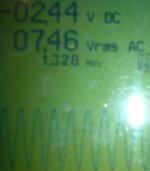
No matter what I try in caps values, I can't get rid of those 2.3MHz oscillations with the LM49170 OPAMP.
I tried changing C109, C102, C103 and local feedback from Pin6 to Pin2 soldered directly onto the OPAMP.
No case was better that 10mV oscillations at ~2.3MHz.
Values I've worked with are ranging from 5.5pF to 220pF on local feedback and 33pF-210pF on C102, C103.
Best regards,
/Bo
Idefixes said:Some more little question : does linx design need some arragement to use 2SC5200/2SA1943 (changing in caps small value?)? I have this interrogation beacause in some other design, such as symasym, it was the case comparing to the MJL3281/MJL1302 use. Thoshiba one are oscillating with the original design.
reagrds Marc
I found answer in Jan post#136.
Marc
****!!!!
I changed C109 to 100pF (I had installed 100nF first - see my other posts)
The everything was OK - tp A > tp C adjusted to 1.4V - tp B to GND = about 30mA
😀
Then I connected transistors Q112 to Q119 - power up - PUFFF.
R138 to R145 and Q107 & Q108 was going in smoke - fuse gone
Now I have changed Q107 & Q108 and the pre-test is again OK - but what do I do next? - Is there anything more I can test before connecting new R138 > R145?
All this sounds a bit scary
Are you messing with other components than the original intended ?
Or have you been unlucky to buy cheap fraud copy transistors ?
Are you messing with other components than the original intended ?
Or have you been unlucky to buy cheap fraud copy transistors ?
I'm a little confused here about all the oscillation problems.
I've done crazy stuff to OPA134, 2134 and OPA627, without any problems whatsoever. And without compensation capacitors in the feedback loop either. What strikes me as odd is that all of those opamp's datasheets recommend supply bypassing values quite a bit larger than what's used here. What is the impedance of the next stage that the opamp is trying to drive? Should you go up to a microfarad or five for bypass caps? paralelled to the 100nf that's already there.
I've been meaning to ask about the way the opamp is conencted as well - the signal on the negative input with the feedback on the positive. It's not very ofeten that you see this configuration, what is the intended purpose?
I'm planning to build one myself, so I decided to start asking questions about the parts I don't understand.
Atilla said:
I've been meaning to ask about the way the opamp is conencted as well - the signal on the negative input with the feedback on the positive. It's not very ofeten that you see this configuration, what is the intended purpose?
Inverting power stage.
- Status
- Not open for further replies.
- Home
- Amplifiers
- Solid State
- Official LYNX Power Amp builder’s thread