Is unnecessary to use a better supply for input IC. Stabilised supply with zener diodes is absolutely adequate. This solution is used in better high end amplifiers than Lynx. I write about schematics from Upupa Epops etc.
Hello there LYNX-experts!
Today I fired my two cards up to perform the pre-test, BUT I had already soldered the output devices in place. Is it still possible to perform the pre-test?
The reason I'm asking is because between A and C I have fluctuating 30-80 mV, and between b and GND I have approx 175 mV. This is on both cards, so I guess it's some systematical error on my side. Nothing changes with the bias pot.
I'd be grateful for any help. I have measured the zener voltage, it's 15V on both cards, and the rest of the voltage (46V) is over the zener resistors (2x4,7k in parallell, as per Jan's suggestion).
Best regards,
/Bo
EDIT: Perhaps I can still perform the pre-test, if I ground the output stage? Maybe that GND-point is drifting about?
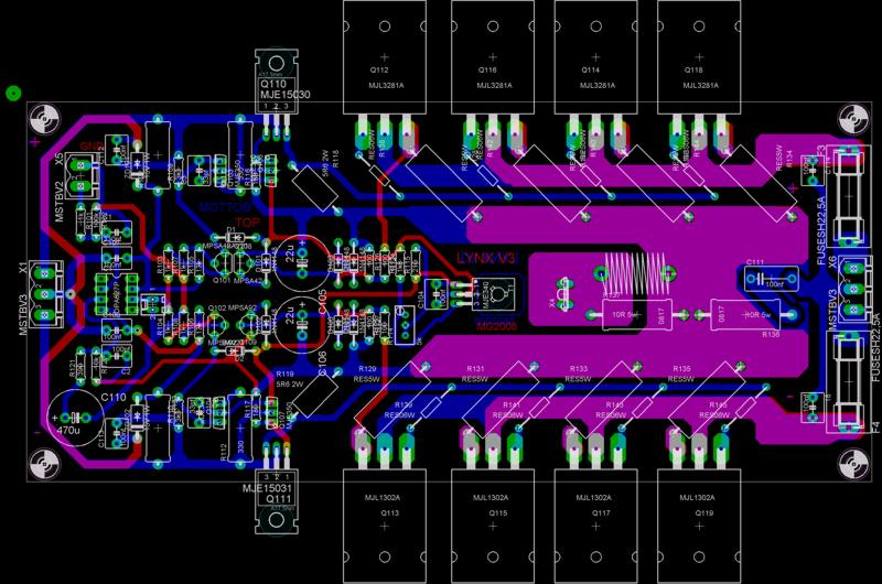
Board for testing and tune:
[IMG=http://img84.imageshack.us/img84/5751/net2jk7.th.jpg][/IMG]
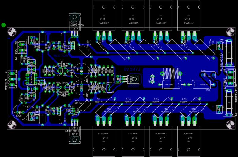
Finalized amplifier:
[IMG=http://img98.imageshack.us/img98/4287/net4ju1.th.jpg][/IMG]
Don´t be scarred, OPA27 is here only for tuning. Real amplifier runs with LME49710 🙂 .
[IMG=http://img84.imageshack.us/img84/5751/net2jk7.th.jpg][/IMG]
Finalized amplifier:
An externally hosted image should be here but it was not working when we last tested it.
[IMG=http://img98.imageshack.us/img98/4287/net4ju1.th.jpg][/IMG]
Don´t be scarred, OPA27 is here only for tuning. Real amplifier runs with LME49710 🙂 .
bomellberg said:Anyone got any suggestions for my problem description above? Any help is most welcome.
/Bo
Did you recalculate zener resistors? Did you measured Q110-113? Are they OK? Did you measured voltages between B and E electrodes of all transistors?
The reason I'm asking is because between A and C I have fluctuating 30-80 mV, and between b and GND I have approx 175 mV. This is on both cards, so I guess it's some systematical error on my side. Nothing changes with the bias pot.
I'd be grateful for any help. I have measured the zener voltage, it's 15V on both cards, and the rest of the voltage (46V) is over the zener resistors (2x4,7k in parallell, as per Jan's suggestion).
Hi Bo,
How did you do these measurements?
Did you have the input shorten to Gnd?
A fluctuating Voltage between tp A and C could indicate some kind of oscilliation. Have you checked with an oscilloscope?
Did the drivers got very hot during your testing?
Jan;
If I grounded the input, I got 0V between A and C. The drivers were never hot at all.
Sadly, yesterday when I was testing it again, it went into flames... I had grounded the output stage as well, and ALL the R138 to R145 just exploded, along with some other 0,6W resistors further up the line.
Hopefully, I can clean the card and replace the bursted components. I also hope that none of the MJL's are goners.
masteramp;
I recalculated the zener resistors to match my approx 61.5V rails. (61.5 - 15) / 0.02 = 2325, so I paralelled two 2W 4,7k resistors.
If I grounded the input, I got 0V between A and C. The drivers were never hot at all.
Sadly, yesterday when I was testing it again, it went into flames... I had grounded the output stage as well, and ALL the R138 to R145 just exploded, along with some other 0,6W resistors further up the line.
Hopefully, I can clean the card and replace the bursted components. I also hope that none of the MJL's are goners.
An externally hosted image should be here but it was not working when we last tested it.
masteramp;
I recalculated the zener resistors to match my approx 61.5V rails. (61.5 - 15) / 0.02 = 2325, so I paralelled two 2W 4,7k resistors.
Bo;
I'm sorry to hear/see the result of your testing 🙁
Next;
What do you meen by
Did you actually connect speaker out to Ground
I guess that the image you posted here has been downsized.
Could you email me the high resolution picture?
I'm sorry to hear/see the result of your testing 🙁
Next;
What do you meen by
???I had grounded the output stage as well
Did you actually connect speaker out to Ground
I guess that the image you posted here has been downsized.
Could you email me the high resolution picture?
I guess he has quite powerfull capacitor bank at his PSU .... 😉, to support the short by enough energy.
Jan;
The output stage has a three way power supply connector, with +V GND -V. I connected this GND (the middle pin) to ground (same as on the input side), but not the rail voltages.
Please see the higher res pictures at:
http://www.mellberg.org/LYNX/DSC_4805.JPG
http://www.mellberg.org/LYNX/DSC_4807.JPG
PMA;
Yes, there is quite a lot of uF in my bank. 64400 uF per channel.
AndrewT;
I have a bulb which I have tested my PSU with. Please elaborate how I can use this to avoid future damage.
Although it's a sad experience, I also see it as learning. This is my very first electronics experiment, and I'm having fun all the way! 🙂 I'm on my way now to purchase some fuses and fuse holders. I'm not blowing up the other channel as well!!
Best regards,
/Bo
Hi,
the bulb tester should be used every time you first start a new project or modify an existing project.
At switch on the start up current heats the bulb filament. This is a PTC resistor. If the high current continues the filament gets hotter and turns "on". This limits the voltage sent to the transformer and as a result limits the output voltage of the transformer.
In your example of a dead short across the output I would expect the bulb to drop >95% of the mains supply voltage and the transformer to see just 5% of mains voltage (and also produce just 5% of it's rated VA).
The short will pull down the secondary voltage to less than 5% of rated output voltage, maybe as low as 1/4 to 1/2 of rated turns ratio. Expect a 50-0-50Vac transformer to put out just 0.6 to 1.2V per winding.
Hardly enough to pass the rectifier and the main smoothing caps will charge to just a half volt or so. The shorted amplifier survives, nothing blows up, your bulb is alight and you say "what the f..k" 😕 and switch off and recheck your modification.
No fuses blown, no money burnt.
AHH!
AndrewT;
So, you connect it in series with the power supply to the amp? That makes sense, too bad I didn't come to think of it. Anyway, I have now purchased a bunch of 0,5A fast blowing fuses. Hopefully I will come to a conclusion before I run out of those.
The question remains: Can I perform the pre-test with the output devices in place? Or do I have to solder them off, before continuing with the other board?
Best regards,
/Bo
Bo;
The light bulp connects in series with one of toroids primary windings (230VAC in your case) 😉
As the base resistors to the output devices has blown, just remove these and make the pre-test without fitting new ones......
I'm glad to hear that you haven't lost your guts to tame this beast 😉
The light bulp connects in series with one of toroids primary windings (230VAC in your case) 😉
As the base resistors to the output devices has blown, just remove these and make the pre-test without fitting new ones......
I'm glad to hear that you haven't lost your guts to tame this beast 😉
Why grounding the output?
Bosse, did you really ground the speaker output? Why? Don't you have any fuses?
Bosse, did you really ground the speaker output? Why? Don't you have any fuses?
PMA;
Even I (when first designing this amp way back) never managed to provide such damage......
It must have been quite a nice lightshow (maybe to celebrate the asian new year) 😉
😀I guess he has quite powerfull capacitor bank at his PSU .... , to support the short by enough energy.
Even I (when first designing this amp way back) never managed to provide such damage......
It must have been quite a nice lightshow (maybe to celebrate the asian new year) 😉
Hey.
I think this is best approach.
1. Build LYNX following the original 100%
2. When you have this good working, you can start make modifications.
If you like to, you can ask what ACD thinks about your plans.
After all, he 'knows' his design the best.
To start making your own modified version right away, may often result in some problems.
This is a general advice not only for this amplifier.
Because the published original version should have best chance to work.
Regards 🙂 Lineup - trying to be a wise-head
- Status
- Not open for further replies.
- Home
- Amplifiers
- Solid State
- Official LYNX Power Amp builder’s thread