Re: LM431's....
Koinichiwa,
Using 6V batteries will force you to use a very low value of resistor, as the battery when fully discharged will have a terminal voltage of only around 5V. When fully charged the Battery will have a terminal voltage of around 6.2...7.4V. So, in the fully charged case you need to drop up to 2.4V across the resistor, in the fully discharged case you will need to drop under 0.5V.
The LM431 will need at least a few mA current flowing to operate correctly. So, if we assume a Current Draw of 25mA for the chip pin supplied and (say) 3mA for the LM431 the resistor will have to be 0.5V/0.028mA = 17.8 Ohm (18R NPV).
If we now have 2.4V across the resistor, the current flowing will be 2.4/18 = 0.133A or 133mA. Of this current 25mA enter the supplied Chip's pin, the rest flows into the LM431. As the limit for the LM431 is given as 100mA you are potentially in trouble already.
More importantly, the Chip will dissipate 0.54W in heat, more than I'd be happy with, given the case is only TO-92 a heat dissipation of 0.54W will raise the Chip temperature under ideal conditions (good airflow to avoid heating up the area near the IC) by 85 centigrade, giving with 30 Centigrade ambient temperature 115 centigrade chiptemperature, more if the ambient air is heated up. In my view there is simply not enough voltage headroom in this to regulate, as the TL431 is limited in current and dissipation.
This means you will need to use 12V Batteries, which will then require between 5.5V and 9.4V to be dropped across the resistor. Lets now take the same chip pin, drawing 25mA. At the "normal operation" point for the Battery (around 12.5V) we would want ideally to have the same shunt current as the pin draws, so we need to drop 7.5V for a currnet of .05A, giving 150 Ohm.
At the maximum voltage of 9.4V we have 63mA flowing, of this38mA pass through the LM431, resulting in 0.19W heat rejection and a chiptemperature rise above ambient temperature of 30 Centigrade. At the Minimum voltage across the resistor (5.5V) the currnet flowing is 37mA, of which 12mA pass through the LM431.
As you can see, using 12V batteries we get great regulation over teh charge/discharge cycle of the batteries, while with 6V batteries we are in trouble at full charge with overloading the IC or at full discharge with not having any more current to regulate.
If you absolutely INSIST on 6V batteries you need to look for chip regulators with << 1V dropout Voltage, the LM/TL431 shunt regulator is not very good with as little holtage headroom as that, in fact, NO regulator is.
Sayonara
Koinichiwa,
RichardJones said:So... If I use 6v batteries to power the CS8412, TDA1543 and 74VHC74..
and use LM431's on all power/gnd combo's... what value of that initial resistor should I use?
Using 6V batteries will force you to use a very low value of resistor, as the battery when fully discharged will have a terminal voltage of only around 5V. When fully charged the Battery will have a terminal voltage of around 6.2...7.4V. So, in the fully charged case you need to drop up to 2.4V across the resistor, in the fully discharged case you will need to drop under 0.5V.
The LM431 will need at least a few mA current flowing to operate correctly. So, if we assume a Current Draw of 25mA for the chip pin supplied and (say) 3mA for the LM431 the resistor will have to be 0.5V/0.028mA = 17.8 Ohm (18R NPV).
If we now have 2.4V across the resistor, the current flowing will be 2.4/18 = 0.133A or 133mA. Of this current 25mA enter the supplied Chip's pin, the rest flows into the LM431. As the limit for the LM431 is given as 100mA you are potentially in trouble already.
More importantly, the Chip will dissipate 0.54W in heat, more than I'd be happy with, given the case is only TO-92 a heat dissipation of 0.54W will raise the Chip temperature under ideal conditions (good airflow to avoid heating up the area near the IC) by 85 centigrade, giving with 30 Centigrade ambient temperature 115 centigrade chiptemperature, more if the ambient air is heated up. In my view there is simply not enough voltage headroom in this to regulate, as the TL431 is limited in current and dissipation.
This means you will need to use 12V Batteries, which will then require between 5.5V and 9.4V to be dropped across the resistor. Lets now take the same chip pin, drawing 25mA. At the "normal operation" point for the Battery (around 12.5V) we would want ideally to have the same shunt current as the pin draws, so we need to drop 7.5V for a currnet of .05A, giving 150 Ohm.
At the maximum voltage of 9.4V we have 63mA flowing, of this38mA pass through the LM431, resulting in 0.19W heat rejection and a chiptemperature rise above ambient temperature of 30 Centigrade. At the Minimum voltage across the resistor (5.5V) the currnet flowing is 37mA, of which 12mA pass through the LM431.
As you can see, using 12V batteries we get great regulation over teh charge/discharge cycle of the batteries, while with 6V batteries we are in trouble at full charge with overloading the IC or at full discharge with not having any more current to regulate.
If you absolutely INSIST on 6V batteries you need to look for chip regulators with << 1V dropout Voltage, the LM/TL431 shunt regulator is not very good with as little holtage headroom as that, in fact, NO regulator is.
Sayonara
Finised my first I2S in DAC
I have yesterday finised my first DAC. I have used 4 x TDA 1543, I have for now implemented plugable jumpers that makes it possible to do some comparising.
I am feeding the DAC directly I2S out of my CDPRO2, as digital interlink I use approx 60 cm of CAT5 twisted pair which works outstanding.
The first results are as follows:
Using 1k Ohm I/V resistor:
- With two TDA's the sound is a little "flat".
- With three TDA's I begin to hear some distortion.
- With four TDA's the DAC only gives distortion, something seemed to be wrong in this setup.
The above is done with 8 VDC, when lowering the DC voltage below 7,5V (1 to 3 TDA's) distortion is getting mutch bigger.
I lowered the I/V to 500 Ohm:
- One and two TDA's are just not enough.
- With three TDA's things are getting great.
- With four TDA's the DAC sounds fantastic!! very dynamical and clear.
No distortion can be heared. The DC voltage can be changed between 5V and 8V without real differences in sound.
Type of I/V resistor:
I have tested three types: Riken Ohm, VTC Tantallum and Kiwame.
- VTC Tantallum was to "thin".
- Riken Ohm sounded good with nice "tight" highs an lows.
- Kiwame is very close to the Riken but a little more "mellow".
(Sorry for the way I try to discribe sound)
Since I decided that I need an I/V resistor of 500 Ohm I tested the above types parallel to each other. The Riken parallel to the Kiwame is giving me the best sound.
Everything is there with an amazing presence, never heared this like this before.
Peter
Or a single chip, 3x1k and a 6V supply ?

BTW: I would suggest to first find a good configuration with cheapo resistors/pots and then use $$$ ones. You have to lower the I/V resistor when you parallel DACs, so three DACs means three times lower I/V!
Fedde
BTW: I would suggest to first find a good configuration with cheapo resistors/pots and then use $$$ ones. You have to lower the I/V resistor when you parallel DACs, so three DACs means three times lower I/V!
Fedde
Re: LM431's....
If you have batteries with low internal resistance you could try to put the batteries directly on the DAC. I would use a diode in series for the 74VHC74 and the CS8412 (choose a diode with a 0.6-0.7 V drop). Use suitable bypass caps. (eg. 22 uF BG NX 6.3V or somewhat larger)
Fedde
RichardJones said:So... If I use 6v batteries to power the CS8412, TDA1543 and 74VHC74..
and use LM431's on all power/gnd combo's... what value of that initial resistor should I use?
Should I use 2x 1K resistors across the LM431's like in the schematics?
If you have batteries with low internal resistance you could try to put the batteries directly on the DAC. I would use a diode in series for the 74VHC74 and the CS8412 (choose a diode with a 0.6-0.7 V drop). Use suitable bypass caps. (eg. 22 uF BG NX 6.3V or somewhat larger)
Fedde
Re: Finised my first I2S in DAC
Koinichwa,
Sorry to say so, but "YOU CANNOT DO THAT". Okay, you can "technically" do that, as you have. But diong what you did will give totally wrong results. If you doble the number of DAC IC's you MUST halve both the reference and the I/V resistors. If you quadruple the DAC IC's you MUST quarter the involved resistors.
Moreover, while 500 Ohm may work okay with 4 Chips, 5V and your test CD I suspect they will thorw up wobblies still in some cases. All these resistors follow simple mathematical rules and can be calculated for "theortically best values".
I'd suggest sorting the operating points out and then to start experimenting with multiple chips while scaling the resistors inversely (1 Chip R=1*R, 2 Chip R = 0.5 * R, 4 Chip R = 0.25 * R).
Sayonara
Koinichwa,
Peter K said:I have yesterday finised my first DAC. I have used 4 x TDA 1543, I have for now implemented plugable jumpers that makes it possible to do some comparising.
I am feeding the DAC directly I2S out of my CDPRO2, as digital interlink I use approx 60 cm of CAT5 twisted pair which works outstanding.
The first results are as follows:
Using 1k Ohm I/V resistor:
- With two TDA's the sound is a little "flat".
- With three TDA's I begin to hear some distortion.
- With four TDA's the DAC only gives distortion, something seemed to be wrong in this setup.
The above is done with 8 VDC, when lowering the DC voltage below 7,5V (1 to 3 TDA's) distortion is getting mutch bigger.
I lowered the I/V to 500 Ohm:
- One and two TDA's are just not enough.
- With three TDA's things are getting great.
- With four TDA's the DAC sounds fantastic!! very dynamical and clear.
No distortion can be heared. The DC voltage can be changed between 5V and 8V without real differences in sound.
Sorry to say so, but "YOU CANNOT DO THAT". Okay, you can "technically" do that, as you have. But diong what you did will give totally wrong results. If you doble the number of DAC IC's you MUST halve both the reference and the I/V resistors. If you quadruple the DAC IC's you MUST quarter the involved resistors.
Moreover, while 500 Ohm may work okay with 4 Chips, 5V and your test CD I suspect they will thorw up wobblies still in some cases. All these resistors follow simple mathematical rules and can be calculated for "theortically best values".
I'd suggest sorting the operating points out and then to start experimenting with multiple chips while scaling the resistors inversely (1 Chip R=1*R, 2 Chip R = 0.5 * R, 4 Chip R = 0.25 * R).
Sayonara
DEEP SIGH...
Hi,
Does anyone actually understand I/V, or Ohm's law for that matter?
Crickey, you can discuss subjective differences like that till kingdom come...
And I mean you TL...
Stop wasting our time guys and go back to the basics...it's getting long in the teeth.🙁
Back to my bunker,😉
Hi,
Does anyone actually understand I/V, or Ohm's law for that matter?
Crickey, you can discuss subjective differences like that till kingdom come...
And I mean you TL...
Stop wasting our time guys and go back to the basics...it's getting long in the teeth.🙁
Back to my bunker,😉
Frank,
I don't get it, why discurage someone as TL who is trying to help other DIY's who have less experiance or are not EEs?
We are happy to have you and many other experianced audio professionals and they all deserve to be priced when giving advice or helping other members, IMO.

I don't get it, why discurage someone as TL who is trying to help other DIY's who have less experiance or are not EEs?
We are happy to have you and many other experianced audio professionals and they all deserve to be priced when giving advice or helping other members, IMO.
OH DEAR...TYPOS TYPOS.
Hi,
Gossh...
That's the last thing I want...
Damn...that should have read: And I DON'T mean you TL.
Oh boy I shouldn't be allowed near a keyboard...😱
Sorry about that guys...and thanks Tony for pointing to the mistake...And no, it wasn't a Freudian slip.
Time to hit the sack. I'm slipping...
Hi,
Gossh...
I don't get it, why discurage someone as TL who is trying to help other DIY's who have less experiance or are not EEs?
That's the last thing I want...
And I mean you TL...
Damn...that should have read: And I DON'T mean you TL.
Oh boy I shouldn't be allowed near a keyboard...😱
Sorry about that guys...and thanks Tony for pointing to the mistake...And no, it wasn't a Freudian slip.
Time to hit the sack. I'm slipping...
 No, that can't be true...
ok... so maybe a LM431 and MPSA18?
Does anyone have a circuit that includes a LM431 and a series pass transistor? I have a bunch of MPSA18's....
Can I use 6v batteries in this appliation? Or should I still go with the 12v?
Thanks!
Does anyone have a circuit that includes a LM431 and a series pass transistor? I have a bunch of MPSA18's....
Can I use 6v batteries in this appliation? Or should I still go with the 12v?
Thanks!
Re: CDM12
It has I2S output.
TV Man said:Hi,
Does anyone know if the CDm12 at Stein Music has I2S output??
Thanks
It has I2S output.
Re: ok... so maybe a LM431 and MPSA18?
Koinichiwa,
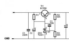
How about the one from the Datasheet (may be the TL431 Datasheet)? Or the attached one?
Well, if make at least 3mA flow at 5.5V Battery Voltage R1 must become around 366R (how about 360R). The cathode of the LM431 will be at 4.4V, around 0.6V below the output Voltage of 5V, hence the voltage across the resistor is 1.1V).
In this case (R1 = 360R) the current flow through the LM431 at 7.2V (battery fully charged) will be 7.8mA, both are values of current well safe.
Of course you loose all the advantages of a (local) shunt regulator by doing so and you may very well simply use a good quality 3-Pin fixed 5V low dropout regulator instead...
Sayonara
Koinichiwa,
RichardJones said:Does anyone have a circuit that includes a LM431 and a series pass transistor? I have a bunch of MPSA18's....
How about the one from the Datasheet (may be the TL431 Datasheet)? Or the attached one?
RichardJones said:
Can I use 6v batteries in this appliation? Or should I still go with the 12v?
Well, if make at least 3mA flow at 5.5V Battery Voltage R1 must become around 366R (how about 360R). The cathode of the LM431 will be at 4.4V, around 0.6V below the output Voltage of 5V, hence the voltage across the resistor is 1.1V).
In this case (R1 = 360R) the current flow through the LM431 at 7.2V (battery fully charged) will be 7.8mA, both are values of current well safe.
Of course you loose all the advantages of a (local) shunt regulator by doing so and you may very well simply use a good quality 3-Pin fixed 5V low dropout regulator instead...
Sayonara
attached one?
I am missing something?
I don't see an attached schematic with series regulator info.....
Yeah I may just use the LM431 datasheet info....
How does PSRR and stuff like that change with the series pass transistor?
I am missing something?
I don't see an attached schematic with series regulator info.....
Yeah I may just use the LM431 datasheet info....
How does PSRR and stuff like that change with the series pass transistor?
Re: attached one?
Koinichiwa,
Gomen.
I forgot to attach.
Sayonara
Koinichiwa,
RichardJones said:I am missing something?
I don't see an attached schematic with series regulator info.....
Yeah I may just use the LM431 datasheet info....
How does PSRR and stuff like that change with the series pass transistor?
Gomen.
I forgot to attach.
Sayonara
Attachments
values
So what are good starting values for C2 and the output capacitor?
100uf?
So does R1 stay the same then for any input voltage? 12v or 6v to regulate down to 5v?
Thanks!!!
So what are good starting values for C2 and the output capacitor?
100uf?
So does R1 stay the same then for any input voltage? 12v or 6v to regulate down to 5v?
Thanks!!!
From this thread:
http://www.diyaudio.com/forums/showthread.php?s=&threadid=14033&perpage=15&pagenumber=3
Where would we be without the Search function ? 😉
http://www.diyaudio.com/forums/showthread.php?s=&threadid=14033&perpage=15&pagenumber=3
I now have further evidence. Using a TL431 series pass regulator, I have found it beneficial to optimise the ps for lowest noise in situ. I find that I am ending up with >150 uf OSCon on the output to the clock, 47 uf across the TL431, and 100 uf OSCon across the input inductor. Substituting OSCons for lytics result in quite large decreases in noise voltages. This is expensive due to the cost of the OSCons but for a high end system may be worth it.
Where would we be without the Search function ? 😉
Oke I have got the message
Thank you for pointing me to the faulty test results, regarding the parallel TDA 1543 configuration, that I posted yesterday.
I will study some more and do it over again. Indeed I am not an experienced DIY of EE.
Is the group interested in the results or has these comparisons been posted many times before? I am a member since some weeks so I do not have a complete overview.
Peter
- Status
- Not open for further replies.
- Home
- Source & Line
- Digital Source
- Non Oversampling DAC-complementing CD-PRO