Congratulations, greyhorse! It's fantastic that your build was a success & you enjoy the sound. My tastes align with yours; when driven by a Noir HPA, I also prefer the Fostex TR-X00 (ebony), over the Sennheiser HD-650.
Reading through the Noir thread, and its predecessor the "T2" thread (linked in post #1), you'll see that readers have discussed a large number of potential modifications to Noir. Some of them were tried experimentally, and others were vigorously advocated but never actually built. One of the least "invasive" tweaks, requiring no desoldering or surgical modifications to the PCB, is to replace the SMPS wall wart that delivers 24VDC @ 400mA. Either with a higher quality SMPS, or an SMPS fitted with very aggressive LC filtering, or a linear supply. All of this takes place outside the Noir chassis and is therefore easily reversed for quick Before vs. After listening tests.
Reading through the Noir thread, and its predecessor the "T2" thread (linked in post #1), you'll see that readers have discussed a large number of potential modifications to Noir. Some of them were tried experimentally, and others were vigorously advocated but never actually built. One of the least "invasive" tweaks, requiring no desoldering or surgical modifications to the PCB, is to replace the SMPS wall wart that delivers 24VDC @ 400mA. Either with a higher quality SMPS, or an SMPS fitted with very aggressive LC filtering, or a linear supply. All of this takes place outside the Noir chassis and is therefore easily reversed for quick Before vs. After listening tests.
Mark,
The power supply change was something I was thinking about already, and since I have a lot time on my hands, I went with it. I already had a CRCRC filter built up (C=18000uF and R=6.7 ohms).
Keeping in mind all the caveats of this being in my system and these being my ears - the stock Noir was a little too polite for my tastes and a bit too airy. It also lacked in bass. The power supply completely changes this and adds noticeable body, but goes too far with a very aggressive in-your-face presentation but with an absolutely HUGE increase in transparency. This being a passive PS, I’m at 21V going into the board, so the operating point change might have a lot to do with how it sounds however. Definitely a worth while experiment for the 30 minutes it took to mock it up.
![url], on Flickr](/community/proxy.php?image=http%3A%2F%2F%5Burl%3Dhttps%3A%2F%2Fflic.kr%2Fp%2F2iMzX7v%5D%5BIMGDEAD%5Dhttps%3A%2F%2Flive.staticflickr.com%2F65535%2F49742624013_475cd1c338_h.jpg%5B%2FIMGDEAD%5D%5B%2Furl%5D%5Burl%3Dhttps%3A%2F%2Fflic.kr%2Fp%2F2iMzX7v%5DNoir%5B%2Furl%5D+by+%5Burl%3Dhttps%3A%2F%2Fwww.flickr.com%2Fphotos%2F68511689%40N08%2F%5Dtokyo+stardust%5B%2Furl%5D%2C+on+Flickr&hash=e36c101dfc8bd9913f5b5749f35b2ac0)
The power supply change was something I was thinking about already, and since I have a lot time on my hands, I went with it. I already had a CRCRC filter built up (C=18000uF and R=6.7 ohms).
Keeping in mind all the caveats of this being in my system and these being my ears - the stock Noir was a little too polite for my tastes and a bit too airy. It also lacked in bass. The power supply completely changes this and adds noticeable body, but goes too far with a very aggressive in-your-face presentation but with an absolutely HUGE increase in transparency. This being a passive PS, I’m at 21V going into the board, so the operating point change might have a lot to do with how it sounds however. Definitely a worth while experiment for the 30 minutes it took to mock it up.
Last edited:
Another mod that should be reasonably easy to implement is bypassing the three series-connected diodes (1N4007 or whatever those were) with a large capacitor of something like 3300 µF up in both channels, polarity observing. Simulation indicated something like a 13 dB reduction of distortion if memory serves. These diodes are essentially acting as some (rather nonlinear) source degeneration where all you really want is some level shifting, so loop gain suffers.
Last edited:
sgrossklass, thanks for the suggestion.
I’d bought both the recommended Nichicon output caps as well as the Panasonic FKs that are in there now, so the diode bypass couldn’t have been easier. Overall the amp now sounds less smooth than without the bypass caps, but I’ll let the caps work in over-night before I make a final determination.
With the linear PS the Fostex TH-X00s are too agressive to sound any good, so I’ve switched back to the Sennheisers. Applying EQ to raise the bass and lower the mids, the HD-650s sound pretty balanced now, but are still lacking in bass. One amazing thing is the COMPLETE lack of Sennheiser veil with this combo. Quite an accomplishment!
A big thanks to Mark for sharing this with us! Keep the mods coming! I’m quarantined, but have a pretty large parts bin...
The bypass caps around the diodes was fun to play with, but overall I think I prefer without. Adding the caps added weight and solidity to the overall presentation which made instruments feel they simply appeared in my head without having gone through any transducer. This was particularly welcome on the bass which changed to being taut and punchy instead of one-note. I always assumed this was how bass on HD-650s was always going to sound, so it’s good to know it’s possible to scale these up.
That being said, gone was the airiness and the organic fluidity that I like about this design. I might put the caps back later if other changes allow for it, but for now they stay out.
That being said, gone was the airiness and the organic fluidity that I like about this design. I might put the caps back later if other changes allow for it, but for now they stay out.
Hi all, I'm new here and very interested in building my first DIY project. It looks like the Noir project could be done as a beginner. Let's see how far I get with it. ;-)
Unfortunately I have already the first question to you guys. The Nichicon transistor (URS1E332MHD, C26/C76) is missing on Mouser. Which one would you suggest as a replacement?
Unfortunately I have already the first question to you guys. The Nichicon transistor (URS1E332MHD, C26/C76) is missing on Mouser. Which one would you suggest as a replacement?
Mitoc, any of these ought to work nicely
3300 uF 7.5 mm Aluminum Electrolytic Capacitors - Radial Leaded | Mouser
They all have the same lead spacing (7.5 mm) as the one in the BOM, with the same diameter body (18 mm) or smaller. They're all relatively "short" so they won't touch the lid of the 1U-height chassis. They're all extended-lifetime (> 5000 hours), they're all rated to work at high temperatures, and they all have relatively high ripple current ratings.
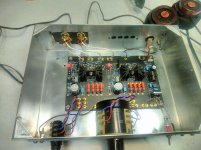
My own Noir with integrated Power Supply
Completed my own Noir version, and it is excellent, very great sounding, fast, immediate, sweet, perfectly silent, a great HP amp!
So here is what I did to the original design:
-Did my own pcb based of picture of the original. Re-route some traces and insured that ground traces separate each channel traces, to try to improve the channel insulation.
-+24V power supply top pcb layers are separated by channel, with a separate last RC supply filter to try to improve the channel separation.
-Added a startup mute timer and mute relay. At startup now the maximum is 8mv at the output. Same thing as shut down, so no more voltage swing.
-Added CRC multi stage filtering, the last stage one per channel to try to eliminate any power supply noise, and try to improve on the channel separation by isolating somewhat each channel supply. My supply ahs a vanishing level of noise. and can't hear a thing at maximum volume, and input shorted.
-Added pcb ventilation holes under the mosfet heatsinks.
-Added an integrated SMPS 24V power supply module with CLC noise filtering, works great, but read on 😉
-Added input bandwith limiting RC filtering and noise choke to reduce input source noise.
-Matched both Mosfet and got perfect gain matching between channel. I had to ordered about 10 MOSFET to get two matched sets.
Thanks for sharing this great design!
Check the picture, playing Chet Baker 'Diane' on my Pono
Attachments

Did also some measurements, this amp perform really, very low THD at reasonable listenign level. Here my preliminary results, with a test lab power supply, All measurements done into a 32R test load, otherwise noted
Vout at Vin 1V, 1kHz: 1.95V, Gain 5.8dB (Don't forget I have an input 100R/220R, 100Pf input filter...)
Max Vin: 3.12V (Vout 6.2V)
THD (1V out, 1Khz): 0.05% into 32 ohms (0.005% open load)
BW (Ref 1Vout, 1Khz): 167Khz
Output square wave is almost perfect (I have an added 22pF at the output...)
Max Vout at startup: 8mv
Last edited:
Now the integrated SMPS Power Supply, it didn't worked as planned. The amp was working fine with the lab power supply, Drain 360ma contact (Amp is biased in Class A). But whne I plugged the SMPS instead, guess what, the module was shuting down on and off, and was never reaching 24V, more like a 0-12V on-off pulse!
Checked the amp with my amp meter in pulse recording mode, gues what? My pcb was sucking 1.8Amp peak at start up, for a very short time, but the SMPS module is overload protected for 115% of the max. specs current, or about 1Amp. So the module was seeing an overcurrent and was entering protection mode. The amp never reach steady state at 360ma and the protection was just kicking...
First I tried to replace the first CRC 0.47R resistor with a surge suppressor CL60 (as used by NP everywhere), it worked! The SMPS started, the current increased, the CL60 got hoter, and devrease it resistance, but I lost about 2V on the supply. And not good at all, if I shutdown, and restarted right away, the CL60 was low in resistance, and the SMPS was again entering protection. Not good...
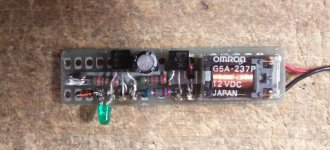
Back on the drawing board. The real solution was to add a 10R resistor at the SMPS output, and once the amp was stabilize (a fraction of second), to short the resistor out for the full 24V supply, and I had to do that within the Mute timer delay (no problem about 45sec mute delay). A softstart circuit 😉
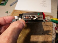
Using parts I had in stock made small point to point softstart timer and bypass relay. It clicks after about 1sec, and work like a charm... I glued it on the side of the SMPS with silicone. This circuit could be implemented in smd part, under the SMPS without problem...
Checked the amp with my amp meter in pulse recording mode, gues what? My pcb was sucking 1.8Amp peak at start up, for a very short time, but the SMPS module is overload protected for 115% of the max. specs current, or about 1Amp. So the module was seeing an overcurrent and was entering protection mode. The amp never reach steady state at 360ma and the protection was just kicking...
First I tried to replace the first CRC 0.47R resistor with a surge suppressor CL60 (as used by NP everywhere), it worked! The SMPS started, the current increased, the CL60 got hoter, and devrease it resistance, but I lost about 2V on the supply. And not good at all, if I shutdown, and restarted right away, the CL60 was low in resistance, and the SMPS was again entering protection. Not good...
Back on the drawing board. The real solution was to add a 10R resistor at the SMPS output, and once the amp was stabilize (a fraction of second), to short the resistor out for the full 24V supply, and I had to do that within the Mute timer delay (no problem about 45sec mute delay). A softstart circuit 😉
Using parts I had in stock made small point to point softstart timer and bypass relay. It clicks after about 1sec, and work like a charm... I glued it on the side of the SMPS with silicone. This circuit could be implemented in smd part, under the SMPS without problem...
Attachments
Last edited:
How did you implement the mute relay, shunt or in series?
The board I'm laying out now has a hard mute on output jack to ground.
And a soft mute on headphone final amp input.
My smps issues were radiated emissions. A filter can eliminate the conducted emi but I
Never solved the radiated. Only physical distance solved it.
Your design looks great...
The board I'm laying out now has a hard mute on output jack to ground.
And a soft mute on headphone final amp input.
My smps issues were radiated emissions. A filter can eliminate the conducted emi but I
Never solved the radiated. Only physical distance solved it.
Your design looks great...
The mute is the following, Relay CT pins connected to the amp circuit output, NC is a 22R/2W resistor to ground, the NO is the output, with a 22p to gnd.
The 22R resistor is there at the output during the mute, already presenting a load similar to the headphone, then when unmuting, the output switches the headphone, and there is almost no difference for the output coupling cap, hence no voltage swing. At least that's the idea...
No radiation noise and/or supply noise at all... Just this start problem that I had to solve...
I used the same module on my B1/Korg preamp pcb and it worked great, but the B1 doesn't have such heavy bias as the Noir... Hence the necessity for the softstart...
My power supply reading are:
Output of the SMPS CLC filter, called Raw 24V = 24.2V
After common first CRC 0.47R/4700uF = 24.0V
then one 1N4004 diode and 0.36R/4700uF resistor/cap per channel = 23.2V each channel at 150ma bias...
Idea of using the 1N4004 diode is to insulate each supply, like a poor man dual mono supply. Same trick is used by Pass...
Forgot to mentionned that I also changed the circuit to be referenced to gnd, with a 24V positive supply... Works like a charm as well.
This way the source input ground is ground...
Last edited:
Great suggestions on this. I was recommending this on the WHAMMY thread earlier as some people were experiencing grounding issues between the modular panels. The simple solution was to sand down the contact points for more solid grounding, but as you said, the easiest way to test/verify solid grounding is as you say, probing with the continuity option on your DMM.
A "star" ground is key I've found in achieving the lowest noise performance and defeating loops, which is why I've typically connected all grounds to this point and this point via a CL60 to chassis/earth in only 1 single place.
This is where my question originally was also around the connection of the ground (not negative PS return) to chassis via a CL60. On the WHAMMy we also connected the RCA input shields + negatives to earth ground via a .1uf 250+ V cap to shunt high frequencies. I plan to do that on my build of the Noir and test it out, but curious as to why I've not seen that here and would appreciate feedback from folks on reasons why.
Thanks!
Sure, feel free to build your D.I.Y. project however you like. If you decide to use the PCB sold in the Store, spend a few minutes "buzzing it out" with the continuity tester / buzzer feature of your DVM. I think you'll find that there is electrical continuity between the ground pads (flywire soldering points) of all four RCA jacks, and also continuity between them and the "ground" terminals of electronic components such as R25. You'll also want to trace the electrical continuity between the PCB mounting holes at the four corners of the board, and RCA ground. Same goes for the "ground" pins of the 6.35mm headphone jack (labeled "G" and "L" on the schematic and on the board).
If you discover that continuity exists where you don't want it to exist, you'll either need to route your external flywires differently, or cut traces on the PCB, or use insulating (nylon) bolts & nuts to fasten the PCB to the chassis floor, or ... (insert additional ideas here). And if you discover that two points are not connected, which you feel ought to be connected, then devise a scheme to hook them together.
If you decide to use the front panel PCB that the Store ships along with the main circuit board, you'll want to buzz out its continuity too. In particular you'll want to check the continuity between the body of the ALPS RK27 potentiometer, and the front & rear shielding planes on that PCB. If it's not what you want, make a modification. Or perhaps decide against using that panel after all. I don't think you'll find anything to modify on the rear panel PCB, because all of the jacks (including the DC barrel jack) are insulated from the panel. That PCB does include shielding planes on both sides, however.
I spend a lot of time listening to my Noir, using a mains powered CD player as a source. I don't hear any hum at all. FWIW.
Completed my own Noir version, and it is excellent, very great sounding, fast, immediate, sweet, perfectly silent, a great HP amp!
Congratulations on your success! With all of your modifications, not to mention your own PCB layout, it was an ambitions project. Glad to hear you are delighted with the results.
When it's all buttoned up & installed in a final chassis, please post some photos. I'm sure members would like to see how you arranged the front panel, the rear panel with RCAs or XLRs, the AC mains inlet, and so forth.
Very well done.
Will be rather straight forward using an Hifi2000 enclosure, and with my 2 little rounds ventilation window on top. This amp is cooking!
SB
SB
Hey All!
Started on my Noir yesterday. Board all done except for the backordered L2 core, and 3300uf caps. The 1K resistors were also BO, but had some in my junk box.
Coimment on the BOM: my ALPS pot came without hardware. Don't know if this is an oversight or a FU on Mousers's part.
It has 4 R3,R5 when it appears only two required.
What a BEAUTIFUL board! Truly a pleasure to work on this project.
I've enjoyed all of my DIY and AmpCamp projects. The old 15w Class-A AmpCamp mono blocks still sound great after all these years.
Can't wait to actually *hear* my Sennheiser HD-800 cans via MacBook and Schiit DAC. I have tons of wonderful 24 bit content to peruse.
Cheers!
Frank
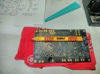
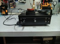
I finished my Noir a few months ago and finally getting around to getting some pics off my tablet. It was a fun little project. I tried to use mostly parts laying around the shop. Hence the retro look. This is the third or fourth project for the case. So the Noir front and rear panels were great for covering all the old holes. The volume pot is an old Shallco 10K pot rescued from an old audio board.
I found that a carpenters pencil worked well for mounting the large resistors.
Thanks Mark for this little gem.🙂
I found that a carpenters pencil worked well for mounting the large resistors.
Thanks Mark for this little gem.🙂
Attachments
Mike2 - lovely build! Whatever you did to clean the PCB of topside flux, worked extremely well. And of course the carpenter's pencil was pure genius! Glad you're pleased with the sound of your Noir.
- Home
- Amplifiers
- Headphone Systems
- Noir, a two transistor headphone amp: class-A, single ended, 150mA bias