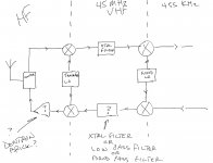
Your image chart isn't right. A superhet receiver without any front end filtering will have two responses. LO + IF and LO - IF. So a receiver with a 101 MHz LO and a 45 MHz IF will respond to 146 MHz and 56 MHz equally well. It is up to the front end filter to reject one of these and pass the other.
LO IF + response - response
101 45 146 56
97 45 142 52
74 45 119 29
66 45 111 21
59 45 104 14
52 45 97 7
48.5 45 93.5 3.5
46.8 45 91.8 1.8
There will also be responses at 2 X LO +/- IF and 3 X LO +/- IF..... each harmonic of the LO will be successively smaller so beyond 2X and 3X are usually non issues, unless you ate Motorola trying to meet 80 db image specs.
The radio will have a 2nd image spec. You will have a 2nd LO at 44.545 MHz or 45.455 MHz to convert your 45 MHz IF to 455 KHz. This puts an image either 910 KHz above, or 910 KHz below the desired receive frequency. The radio's response to this image is determined almost entirely by the selectivity of the 45 MHz crystal, and leakage paths around the crystal through the PCB or wiring.
If you live near, or plan to take the radio to a location near an AM broadcast station a high pass filter to reduce these signals may be needed. A nearby 10 KW radio station can make even the most linear circuits into mixers! Ditto strong FM and TV broadcast stations. AM signals are worse case since the varying RF levels tend to turn a mixer into a blender!
I had a hard time trying to explain this to one of out receiver "experts" at work. An ugly meeting erupted into name calling. I finally convinced our boss to arrange a field trip to a Miami Dolphins NFL game. I specifically requested upper level end zone tickets......These seats are near eye level with three TV transmitting towers 4 blocks away, with a total of 9 TV transmitters, some with an ERP of 1 MEGAWATT each, some only a few MHz away from the desired RX frequency. The expert's radio prototype would not receive anything!
LO IF + response - response
101 45 146 56
97 45 142 52
74 45 119 29
66 45 111 21
59 45 104 14
52 45 97 7
48.5 45 93.5 3.5
46.8 45 91.8 1.8
There will also be responses at 2 X LO +/- IF and 3 X LO +/- IF..... each harmonic of the LO will be successively smaller so beyond 2X and 3X are usually non issues, unless you ate Motorola trying to meet 80 db image specs.
The radio will have a 2nd image spec. You will have a 2nd LO at 44.545 MHz or 45.455 MHz to convert your 45 MHz IF to 455 KHz. This puts an image either 910 KHz above, or 910 KHz below the desired receive frequency. The radio's response to this image is determined almost entirely by the selectivity of the 45 MHz crystal, and leakage paths around the crystal through the PCB or wiring.
a single 30 MHz Low pass filter is adequate for HF reception to 30 MHz.
If you live near, or plan to take the radio to a location near an AM broadcast station a high pass filter to reduce these signals may be needed. A nearby 10 KW radio station can make even the most linear circuits into mixers! Ditto strong FM and TV broadcast stations. AM signals are worse case since the varying RF levels tend to turn a mixer into a blender!
I had a hard time trying to explain this to one of out receiver "experts" at work. An ugly meeting erupted into name calling. I finally convinced our boss to arrange a field trip to a Miami Dolphins NFL game. I specifically requested upper level end zone tickets......These seats are near eye level with three TV transmitting towers 4 blocks away, with a total of 9 TV transmitters, some with an ERP of 1 MEGAWATT each, some only a few MHz away from the desired RX frequency. The expert's radio prototype would not receive anything!
Audio engineers try to get rid of RF.
I have had a couple of designs that put out RF before they were tamed.
We sometimes pick up RF on inputs or speaker cables.
I have had a couple of designs that put out RF before they were tamed.
We sometimes pick up RF on inputs or speaker cables.
Thanks, George. The more I've thought about it, the more yours and Gerhard's earlier comments are sinking in, and making more sense to me.
I don't have real clearly defined goals for this project; they are pretty fluid from day to day. I'm not sure if that's good or bad. It's mostly going to be a start soldering, experiment some, and see where I wind up at, sort of thing.
My first thoughts were something simple, maybe a single band rig for 20 meters, but when I started to block it out, I realized the up conversion scheme really doesn't need band switching in the traditional sense. That's when your comment that the band specific xmtr low pass filter was adequate for the receiver front end, started to sink in.
I'm sort of leaning toward a mobile rig at this point, with a simple control head in the front of the car - volume, tuning, mode, frequency display - , and the radio in the trunk where the battery is located. The only HF mobile I have right now is an FT-817. It's a nice radio, but too menu dependent for easy mobile operation, imo.
Re: high pass filtering on the front end- I have thought a bit about that, per your earlier comment. We don't have any real big MW xmtrs around here. We have a 5 KW station, a 1 KW station, and some smaller ones. The biggest FM xmtr that I'm aware of is that 100 KW station 11 miles north of me.
I was thinking of a five pole low pass filter for the front end, but if I go with a mobile rig, I have a Yaesu screwdriver antenna, so I gain a pretty sharp tuned circuit with that, and three poles might be adequate in the radio.
I'm still thinking about the mixer. I do have a pre fab diode ring mixer, and I've been thinking about that. I'm sort of inclined to go with an active mixer to make the receiver simpler, and pick up some conversion gain, specifically the obsolete TI SN76514 ( TL442CN ). Doubly balanced, low parts count, and the inputs / outputs can be set to 50 ohms on one side and 600 on the other, so easier matching to a low pass filter on the input side, and the xtal filter on the output side.
I haven't thought much about the xmtr, other than thinking about where the sidebands are going to wind up at after multiple conversions. It also occurs to me ( duh ) that the 10 MHz DDS I finally located could be a carrier oscillator for those 10.350 MHz USB/LSB filters that I have. Maybe that's what I was thinking when I got it. I don't know. But I don't have any information on those filters to match in and out of them. I do ( or did ) on the Collins filters.
I've also since found a pile of 260 (262?) KHz Collins mechanical filters.
Win W5JAG
Audio engineers try to get rid of RF.
Some of us have played on both sides of that fence......I have been known to go poking around in a tube amp with an RF spectrum analyzer.
The only HF mobile I have right now is an FT-817.
The only RADIO I have is an FT-817. Unfortunately, I haven't found the time to put up any kind of antenna, so it doesn't matter what radio I have. I live at the bottom of a "holler" with a 150 foot vertical wall of rock just on the other side of the creek behind me, about two miles long, and hills all around, so interference is not going to be a problem, finding a signal to receive might be.
I wandered the property with a broadband antenna on a 20 foot stick connected to a 2.9 GHz spectrum analyzer three years ago before the house was built. No TV, no cellular, 4 weak FM radio stations, and the two way repeater at the prison about a mile away......other than a few random bursts at 2.4 GHZ from someone's WiFi, not much else. When I get a chance I'll string a HF dipole or something between a couple of trees, but until then I'm not in a hurry to make a better radio.
thinking about where the sidebands are going to wind up at after multiple conversions.
If you have a DDS or PLL to swap between the two possible LO's for your second oscillator, the sidebands don't matter, just choose the 2nd LO that works, depending on where everything else falls. I look at the transmitter as the receiver running backwards, If you make your transmit signal at 455 KHz, or even 45 Mhz, then run the same converters in the other direction for TX. Some big name radios do this, but I can't remember right now without digging through my hard drive (Elecraft K3 maybe?).
Several of the Brainiacs in the radio development group created a giant spread sheet to figure out good choices for IF frequencies. I might have an old copy on a hard drive somewhere, but we are limited by parts that are available in a catalog like Digikey or Mouser.
Our radios had impressive specs, which got tougher each year, so the choices got more limited. 45 MHz is a good choice for anything we could DIY for any RF frequency up to 928 MHz. We moved higher and higher to chase the higher specs for image rejection, especially at RF frequencies near 1 GHz. We used 73.35 MHz for broadband UHF radios 380 to 520 MHz, and 109.65 MHz for radios that covered 700 to 900 MHz. These frequencies were chosen for absence of transmitters, and minimal unwanted mixing products.
I had the design of a complete radio that covered 1.7 MHz to 2.5 GHz all planned out when I was at Motorola. Several of us hams would brainstorm up the perfect radio, but were contractually bound not to build anything......Motorola actually owned Yaesu at the time. Now that I could build whatever I wanted, I'm willing to bet that most of those parts aren't available any more. Cell phone tech has a very short product life expectancy.
.... I live at the bottom of a "holler" with a 150 foot vertical wall of rock just on the other side of the creek behind me, about two miles long, and hills all around, so interference is not going to be a problem, finding a signal to receive might be.
I wandered the property with a broadband antenna on a 20 foot stick connected to a 2.9 GHz spectrum analyzer three years ago before the house was built. No TV, no cellular, 4 weak FM radio stations, and the two way repeater at the prison about a mile away......
Well, sounds good, maybe ideal, for EME and sat operations. For HF, I guess it depends on where your hills are. You can get pretty decent gain off the ends of a wire antenna, so you can at least aim away from that rock.
When I was a kid we lived in a bowl, except for a slight opening from about 230 to 270 degrees. I had hills of several hundred feet within a couple of hundred yards. Radio Death Valley. All I could do was maximize my high angle radiation. I did have a real good one hop, HF signal, but it's a really short hop because of the high radiation angle. Back then, DX was VE3 or VE4. XE once in a while.
I now live, triumphantly, a few hundred yards from where I grew up, on the tippy top of that *!@# hill that vexed me so badly as a kid.
I look at the transmitter as the receiver running backwards, If you make your transmit signal at 455 KHz, or even 45 Mhz, then run the same converters in the other direction for TX.
I've got one or two questions about this, but can't post a block diagram right now - sitting at the courthouse .....
Now that I could build whatever I wanted, I'm willing to bet that most of those parts aren't available any more. Cell phone tech has a very short product life expectancy.
Not just cell phone parts, but analog TV IF type chips like CA3065, CA3089, MC1350, etc., that were so DIY friendly are gone or going. MC1496 may also be marked obsolete. Forget about the extended temp range, chip in a can, version of anything. Someone posted in parts that CA3046 is last call. I would have thought CA3046, CA3086, etc., were gone long ago. MC1550, CA3018, CA3028, and CA3053 sure are. Dual Gate MOSFETS? Not common and overpriced when you find them. Through hole slug tuned coils? Looks grim, but CoilCraft still has a line and looks to sell direct from their website. 10.7 MHz cans are gone. I know of exactly one source, ironically, a ham about fifty miles from here. 455 KHz xfmrs are available as of last week .....
Win W5JAG
The LM3046 (originally National, now TI) thru-hole went obsolete last year. The SOIC is listed at digikey, but with zero stock. It's probably the last of the CA3xxx series to be made.Someone posted in parts that CA3046 is last call. I would have thought CA3046, CA3086, etc., were gone long ago. MC1550, CA3018, CA3028, and CA3053 sure are.
There have been many "good parts" (specifically for audio/music synthesizers) from decaded ago that have gone away, such as CA3080 and CA3280. The LM13700 does just about the same thing, but I've read claims the older ones were better.
There's some hope that some of these will come back, made by non-USA companies. This is a remake of National's LM394 supermatched NPN pair:
Voltage Transistors
These (and other remade chips I've seen) are for audio/music synths, but if such companies see a demand for the RF series, they may make them.
The good thing about IF transformers is it's possible to actually wind and make them yourself. I've not seen where anyone has done so, but it seems like it shouldn't be too hard. At least it's a lot easier than making BJTs or dual-gate FETs.Through hole slug tuned coils? Looks grim, but CoilCraft still has a line and looks to sell direct from their website. 10.7 MHz cans are gone. I know of exactly one source, ironically, a ham about fifty miles from here. 455 KHz xfmrs are available as of last week .....
Win W5JAG
......gone away, such as CA3080.....
The CA3080 was recently short-run by Rochester Electronics.
The best (IMHO) DIY supplier is Small Bear Electronics. Steve "Bear" worked with Rochester to make this happen. From reports on guitar-pedal forums, nearly all other sources are nonfunctional fakes. (eBay is full of "3080" things that let pin 5 fly high.)
Disclosure: I have been friendly with Steve but get no kick-back from him.
AFAIK, RCA ("CA" prefix) was the origin of many of the linear types that National ran later, although National made a lot of neat stuff on their own like LM370, LM373, LM375 and many others. I have a bunch of gold pin '3046 types, so I decided not to order any more.
With some add on parts, the '3046/3086 types can be used to replace CA3028 and CA3053.
IF xfmrs can be wound on a toroid, but it's a pain. The 10.7 MHz types are particularly useful because they can be padded down to 3 MHz, maybe lower. Those going obsolete is a bad deal for homebrew.
Win W5JAG
With some add on parts, the '3046/3086 types can be used to replace CA3028 and CA3053.
IF xfmrs can be wound on a toroid, but it's a pain. The 10.7 MHz types are particularly useful because they can be padded down to 3 MHz, maybe lower. Those going obsolete is a bad deal for homebrew.
Win W5JAG
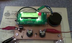
The DDS has arrived. As anticipated, it is quite small - looks about right for a mobile / portable rig. The idea here is to just put the whole DDS board in a control head, and run the RF back to the rig. I don't know how much RF this thing will put out, and whether cable loss will be a benefit or a problem. Using active mixers, I suspect cable attenuation will be a benefit, since I only need 60 -100 mv of RF injection.
Nor do I have any test equipment that can directly measure amplitude at the anticipated LO frequencies, so I will have to improvise something to figure this out indirectly. But at least the project can move forward, now.
Normally, a Friday arrival of a new part is a boon - but not this particular Friday. While I am at least 900+ miles from the nation's premier hamfest, I am but a mere ninety miles from the world's biggest gun show - 11 indoor acres of all things that go bang, which is this weekend, and W5JAG and third harmonic plan on being there.
To muddy the waters further, I was trying to get some data on some of my filters, and wound up at Rob Sherwood's web site. Looking at slideshows of some of his Dayton presentations, he says beginning in 2003, the high performance receiver trend now is back to DOWN conversion in the 5-10 MHz range for a narrow first IF, band pass filters or tracking preselectors, like it's 1975 all over again .....
Regardless, I am committed to a simple up convertor at this point General coverage and no preselector sounds pretty good to me. If I want to go the 1975 way, I can put one of his first IF filters in my R-4C and I'm there .....
Win W5JAG
Attachments

I would have thought CA3046, CA3086, etc., were gone long ago.....AFAIK, RCA ("CA" prefix) was the origin of many of the linear types
The "CA" parts did indeed originate at RCA. My first IC project used an RCA CA3020 1/2 watt "audio amp" IC in 1969 or 1970. Of course I played guitar through it, but it seems that at least one military contractor used it in a servo application. I guess it worked well there, because it went from RCA to Intersil to Harris to somewhere else, and it kept being upgraded along the way. National and others second sourced many of the military parts, and spares were needed for as long as someone was using the end product in the military.
many "good parts" (specifically for audio/music synthesizers) from decaded ago that have gone away, such as CA3080
The original RCA CA3080 in the round metal can either had a design problem or ARP was misapplying it since they all went noisy over time. The hot tip for quieting down a noisy ARP Odyssey was to sky wire a non RCA 8 pin dip 3080 into the VCA in place of the round metal RCA.
In a synth related note, a small company called OnChip has remanufactured the old Curtis Electromusic CEM3340 VCO chip, and are selling them for $15 each.....I got a few to play with. Now if they would only do the VCF chip......
Looking at slideshows of some of his Dayton presentations, he says beginning in 2003, the high performance receiver trend now is back to DOWN conversion in the 5-10 MHz
Whenever two or more engineers are working on a similar project, there will be strong differences of opinion on how things should be done, and if both players are competent designers, both may have valid, but different designs. Often both will meet the published design criteria, but each will have their own benefits and drawbacks. It is often the details that are NOT in the published specs or design criteria that will make or break the different designs in the real world.
Too often Motorola got products out into the real world to find that there were severe problems somewhere because of this. In my 41 year there were 3 major cluster f$^*s due to someone not paying attention to where the image frequency falls. As I alluded to earlier, my demonstration at an NFL game averted number 4 before it happened. It doesn't matter if you meet 80 db of image rejection if the radio has a plastic housing (UHF HT220) and there are powerful TV or cellular transmitters on the image frequency.
Try putting 20 or so good RF engineers in a room and asking them to design a cell phone. It takes months before the name calling and finger pointing stops. After being lead RF guy on several cell phone projects, I had come to the conclusion that either by boss was going to get a phone stuffed up his butt, or I was going to have a heart attack, either way I would be leaving the plant in a city vehicle (cop car or ambulance). I left the phone group before that phone ever shipped. The group imploded in a huge layoff and was eventually sold off a few years later.
There IS NO ultimate clear cut winner as to how to design anything, especially an RF product. There are design goals, and expected use cases, and of course cost, size and power requirements. Each designer must carefully balance all of these.
I brought up the upconversion idea for multi band hand held police radios and was immediately told how stupid I was......."That is stupid, it will never work." I explained the benefits, and the drawbacks, and explained that there were currently MILLIONS of such devices in use today. When it didn't go anywhere, I shut up. Life in the phone group taught me that corporate life expectancy works a lot like the TV reality game show "Survivor." You need to pull your own weight, don't excel at anything (you may be perceived as a threat) and NEVER do anything to threaten the alliance of power. There is one in every group, and it may not always be obvious.
My idea was perceived as a threat by those in control, and I was told later not to attempt to play in their sandbox, which is why I became a transmitter guy. That group was a disaster. The million seller with an upconversion receiver? They are called TV sets and cable boxes. Motorola was the industry leader in cable boxes before they sold that group too, and I had the schematics, and design documents for one of their high spec units. There are lots of reasons to do upconversion, but the big one is image rejection. With a 1.2 GHz first IF, the image is in the 1 - 2 GHZ region where mega strong signals are few. The drawback is that you need two synthesizers, but we needed them anyway.
.....I will be building one sooner or later.....using cable box saw filters from Mouser.
...... I look at the transmitter as the receiver running backwards, If you make your transmit signal at 455 KHz, or even 45 Mhz, then run the same converters in the other direction for TX .....
Here's what I'm thinking, if you guys can read my chicken scratch.
It may sound counter intuitive, but I think for my skill set, I'm better off keeping the common elements / switching to a minimum, and more or less (mostly more ) keeping the TX and RX strips, separate.
A big question mark I have, is that selectivity element at 45 MHz in the TX strip. Do I even need anything there? If I do, is a low pass filter OK? Or do I need to order another XTAL filter?
Some of this uncertainty relates to the repairability of that Dentron brick. If I can get it going, all my power gain can be after the last TX mixer. If I can't get it going, then I feel like I need to spread the TX gain over a few frequencies for stability purposes, hence do I need a low pass / band pass element at that 45 MHz TX IF?
If that makes any sense.
This is not a rush type decision, but I want to make allowance for this as I build out the RX. I need to get the RX going in at least some type of simple form, so I can run it in the car to proof it and see if I need noise blanking, etc., added in to it.
Win W5JAG
Attachments
hence do I need a low pass / band pass element at that 45 MHz TX IF?
You will need a bandpass element there, probably a crystal filter. Just as with the receiver there will be an image in the transmitter. Lets say you are running your LO at 44.545 MHz and mixing that with 455 KHz to make 45 MHz. The mixer will create the sum (45MHz) and difference (44.09 MHz) frequencies. Lets say that you mix the 45 MHz with a 59.1 MHz 2nd LO to make a 14.1 MHz 20 meter transmit signal. There will also be a 15.01 MHz (out of band) signal which will flow right through your transmitter and out the antenna, possibly torqueing off somebody, including the FCC. A filter is needed to kill the 44.09 MHz image from the mixer. Since the image is only 910 KHz away, a simple LC filter will not be sharp enough.
It is usually cheaper to switch the crystal filter and maybe the IF amp and mixer into the TX path and RX path. Cheaper yes, but more complicated, and maybe not worth the effort for a one off project.
Some of this uncertainty relates to the repairability of that Dentron brick.
How much power are you looking for? If the Dentron was in the 100 watt class the common transistors used were MRF454's. Not sure how available they are any more, but sometimes CB (non)Linears are cheap at swap meets and hamfests. I used to grab them when they were $10 or less just to harvest the silicon and ferrites. I haven't looked for such items in years, so I don't know how available they are now.
I had some spare transistors for that HF brick that I made. I haven't got a clue where they are, or if I still have them, but the first place that I would look is very cold right now. Maybe tomorrow afternoon if it warms up.....it's 30 degrees F right now, and 18 is expected tonight.
The "CA" parts did indeed originate at RCA. My first IC project used an RCA CA3020 1/2 watt "audio amp" IC in 1969 or 1970. Of course I played guitar through it, but it seems that at least one military contractor used it in a servo application. I guess it worked well there, because it went from RCA to Intersil to Harris to somewhere else, and it kept being upgraded along the way. National and others second sourced many of the military parts, and spares were needed for as long as someone was using the end product in the military.
I noticed Intersil has a very specific version of the 3046 transistor array that (veering back on topic of this thread) goes into the gigahertz, and costs $9 each at Digikey.
HFA3046BZ Intersil | Discrete Semiconductor Products | DigiKey
My problem(s) with it are I don't have enough RF knowledge to do anything near that frequency, and the chip is way too expensive for what I would want to use it for (synth audio and/or control voltage exponentiation).
Ahem ... looks like the competition is (pun intended for thermal stabilization) heating up in this area:In a synth related note, a small company called OnChip has remanufactured the old Curtis Electromusic CEM3340 VCO chip, and are selling them for $15 each.....I got a few to play with. Now if they would only do the VCF chip......
Application specific
There's someone (maybe more than one, there's enough activity that I'm losing track of who's reintroducing what) remaking one or more of the SSM chips as well.
I remember a Motorola pager that had a IF that was tunable. They did this to use the crystal for both the first and second LO. Saved some money I guess.
High side injection is a great idea makes tuning easier in some cases especially like a spectrum analyzer.
High side injection is a great idea makes tuning easier in some cases especially like a spectrum analyzer.
..... You will need a bandpass element there, probably a crystal filter.
Thank you, I need to get some parts, so I'll probably order another filter. Surplus Sales of Nebraska has some 4 pole 45 MHz filters for a price that is actually reasonable ( for them ), so I might get one of those for the RX, and use the 2 pole ECS for the TX.
The McCoy 30.1 MHZ / 10.35 MHz filter set that I have apparently came from some type of Collins set, and they have a Collins p/n on them, but that's where the trail goes cold. SSoN actually has NOS on them ( for an outrageous price ), but doesn't offer up any specs. Looking at the other McCoy filters they have, the in/out impedances are all over the place - sometimes not even the same at the input as the output.
How much power are you looking for? If the Dentron was in the 100 watt class the common transistors used were MRF454's. Not sure how available they are any more, ....
I'm pretty flexible - 30 to 50 watts PEP out, would be fine, I think. Dentron claims 250 in / 130 watt out from the brick, but it's way undersized for that power level without forced air. They didn't even put vents in the cabinet. The schematic doesn't ID the power transistors. I'll try to scan and post the schematic next week when I'm back in town. I don't even recall it having any protection to keep the transistors from thermal runaway. It's hard to imagine Dentron using a quality part like an MRF454.
RF Parts has matched pairs of MRF454 for about $100, and lesser wattage ones for, well, less, but not necessarily in matched pairs. Depending on the ferrites and other transistors in it, it might be better to go with 50 Mhz parts if I repair it. I'll just have to open it up and see where I'm at.
Don't go out in the cold just yet - I still have some zero cost options. In the vast trove of unbuilt kits, I have one of Virgil, K5OOR, HF Packer amps, HF Projects for Radio Amateurs the early one that uses MOSFET's ( IFR510?) that is good for 50 watts that I could build out. And that Yaesu FL-110 that sat in the same place on my bench for years - I've verified it works. And it seems like somewhere I have a board for a 10 or 15 watt amp using MRF475's, and I have found a couple of pairs of MRF475's in stock, and a suitable heat sink.
With the tunable LO now in hand, I'm looking forward to being able to make real hardware mistakes as opposed to merely drawings on paper mistakes, I just hope they're not real expensive, or embarrassingly stupid ......
I've also got to build out that stereo FM receiver that I slapped the tuner together for, so several things going on at once. I'm still weighing a big stick, dual push pull SSE boards, or an SPP, maybe hot rodded, maybe flea power, for the outputs ....
Win W5JAG
Last edited:
I just hope they're not real expensive, or embarrassingly stupid ......
The only stupid mistake would be calling CQ for hours only to find that you have been talking to your neighbors TV set.
Don't go out in the cold just yet
I need to go looking for some tubes...after it gets a bit warmer. I have a bunch of stuff stored in a derelict mobile home next door. Somewhere in that trailer is a box full of our RF breadboard experiments that might have found their way around the scrap bin when I left Mot.
We had our own PCB fab in house for everything including multi layer HDI. I asked if they could make me a board with 2 layers of Rogers Duroid stacked on 2 layers of FR4 with an aluminum heat spreader in the middle....."yeah, we will try it, but it might take a day or two." They built it, it worked. It was for a 20 watt LTE transmitter on 2.5 GHz. Simple 2 layer boards were made in 6 hours. Sadly it, along with the machine shop and the engineering stock room all were shut down and all the people laid off at the same time I left.
dual push pull SSE boards, or an SPP, maybe hot rodded,
Yeah, I've got a pair of mystery OPT's that I need to hook up. I need to try one of those in a little guitar amp that I made that currently uses a line matching transformer for an OPT.
make real hardware mistakes as opposed to merely drawings on paper mistakes, I just hope they're not real expensive, or embarrassingly stupid .
Well, nearly both. I got back in town late Sunday night, so began trying to figure out the DDS. I got the assembled version, but had some glitches with it. I had it clipped up in a fur ball of jumpers, and once in a while, the display would just unexpectedly blank, which I blew off, thinking it was just the clip leads. Last night, I hard wired it up, and saw the same problem, and a bit worse. The blanking is solved, I think, by reflowing the solder joints on the display.
The bit worse, is, a bit worse - it has a provision to read a dc voltage applied to pin 1 of the microprocessor, ( 0 to + 3.3 ) and output that to a bar graph on the display, and it began doing exactly that, except there was supposed to be no dc voltage at that point. Looking at it on the scope, there was in fact an unwanted 3.3 volts at pin 1 of the microprocessor, and no apparent way to get there, except internal to the microprocessor. Somehow I corrupted the firmware, or the processor.
This was a real problem, as that pin 1 has to be driven high to program the DDS. I made a workaround by jumpering across the meter input to pull pin 1 low, and fashioning a kludge to drive pin 1 back high for programming. The kludge was cutting a pin off an old TTL IC, soldering a thin wire to it (not as easy as it sounds), and pushing this into the pin 1 socket so it is in contact with the real pin 1, and can be driven high to set the prograaming. ( Again, not as easy as it sounds ).
Oleg is sending me a new microprocessor.
In the meantime .....
If these are anything like the Chinese class D audio boards they may be anywhere from somewhat useful to junk.
Well, I don’t know. I haven’t really played with one, so don’t know what to expect.
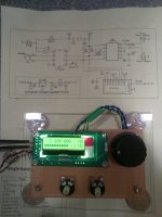
Below are some pics. I have made up a test jig for it so I could go to work on the actual radio - each output goes to a pot for attenuation ( this looks to be a bad idea, and will be modified ), and a small 12 volt supply for powering test boards.
It is anything but clean. The 999 KHz shot is the fixed oscillator. The 1.2 MHz shot is the variable oscillator. Not the time base difference between the two - I believe my cheap scope was having difficulty with the harmonics, but the frequency counter display is correct. The 3.610 MHz capture clearly shows the second and third harmonics. The only good news here is my 1 MHz scope clearly responds out past 10 MHz. I verified the harmonic content with a general coverage receiver. The third is as strong as the fundamental, maybe stronger. The second is weak and raspy. Both DDS outputs exhibit the same behavior.
It may be better at the VHF frequencies I need for a tunable LO and conversion oscillator. It for sure needs to be filtered and conditioned to use as a low HF oscillator.
So, still at square one, maybe backwards one or two ....
Attachments


... It may be better at the VHF frequencies I need for a tunable LO and conversion oscillator. ....
After playing with this a bit more, and doing some belated cursory research on this DDS chip, all this looks to be completely normal behavior. As best I can tell, the kit performs just as described. Properly used, it will be satisfactory for a single band transceiver, which is how it is described.
The data sheet says square wave output, but some of the pics I've now seen just barely approximate a square wave. The waveform ^^ above actually looks pretty good.
The data sheet says nothing about harmonic generation. The third harmonic is just horrendous. I can tune it through the 48 MHz region and stop the scan, and fully quiet my homebrew two meter receiver. The antenna is at least sixty feet away on the roof.
It may or may not be exactly on frequency. I think it's a little off. The firmware allows for exact calibration of the oscillator crystal. I haven't done this, yet, as I expect the crystal to age a bit.
This place: QRP Labs Kits has a bunch of DDS kits based around this chip and for support of this chip, as well as a fair amount of information about it, Arduino code and shield boards to support the chip, BAND PASS filters, etc., .
One of their kits has outputs to switch low pass filters - useful for transmitters, but it's not hard to infer that the same function could be used to switch in band pass filters to kill the harmonics and condition the waveform output to make it suitable for actual use.
Their kits can accept a GPS clock signal and use this as the reference - this resolves the frequency calibration issue.
So, anyway, with suitable filters on each of the outputs to clean things up, this will be a satisfactory LO, but it's not as plug and play as I naively expected. I think the same can be said of anything using this chip.
Win W5JAG
The data sheet says square wave output.......The data sheet says nothing about harmonic generation. The third harmonic is just horrendous.
The Silicon Labs chips use divider technology to make the output frequency, and therefore make square waves of varying duty cycles.
A square wave by definition contains ALL of the odd order harmonics. The distribution of these is defined by the duty cycle. A 50 50 duty cycle affords the highest 3rd harmonic content.
Many of the typical diode or fet ring mixers actually work better when the LO port is driven by a square wave. The reason has to do with minimizing the time where the diodes or fets are operating in their transition (quasi linear) region. Ideally you want one pair of diodes fully conducting while the other pair is off. The transition where the conducting and off pairs are swapped needs to be minimized, because that is when higher order mixing products are generated, and conversion loss increases.
If your synthesizer can operate at twice the needed LO frequency, the usual trick is to run its output through a divide by two flip flop like a 74HC74 to create a pair of complementary square waves with a 50 - 50 duty cycle.
The typical DDS type synthesizer outputs something more like a sine wave, since they have a sine wave look up table in ROM, and just play it through a DAC.
- Home
- Member Areas
- The Lounge
- No RF gear here?