To get the sideband right on twenty meters, I also changed the 9.0015 BFO crystal to one of the new 8.9985 MHz crystals .....
Which was premised on changing the fixed second LO to high side injection at 54 MHz, which I did last night.
And immediately ran into problems (shocker).
The 36 MHz crystal is a fundamental cut, and I built the oscillator for that. It works well; the second harmonic is about 45 dB down from the fundamental. When I put the 54 MHz crystal in, and put a frequency counter on it, it came up at 18 MHz. You guessed it, it's an overtone crystal.
I looked at the output with the FFT, and it showed a textbook distribution of harmonics out to the 4th, which is probably as high as the cheap DSO can resolve. The oscillator is built pretty tight. The inductive/reactive load is a 4.7 uH SMD part mounted *under* the crystal. I can change that without much difficulty, but at present I don't see a way to fit a resonating cap or caps in the available space, even with SMD parts, without significantly rebuilding it.
So, I tried picking out the right harmonic with a tuned circuit in the output and got basically nowhere useful. I used the Toko SMD part discussed of late (among others), and the best I could do was to eliminate the 4th, and bring the (desired) third up to the level of the second, both of which are still about 12 dB under the fundamental. The fundamental never changed, so I guess there is also a leak around the tuned circuit.
For some extra fun, I managed to bust that IF transformer on the output of the second mixer, and that will have to be fixed. I can run the output into the filter on the SG-9 without the transformer, but if I do that, it reduces the conversion gain, a lot, so that would have to be made up somewhere else.
One other thing, the dual gate MOSFET mixer seemed to have some RF isolation between the two gates. The dual JFET emulation appears to have little to no RF isolation between the two gates.
Win W5JAG
why not stay at the fundamental and build a tripler stage ?
wenzel has some examples:
Two-Diode Odd-Order Frequency Multipliers |
wenzel has some examples:
Two-Diode Odd-Order Frequency Multipliers |
A couple of months ago, that was sort of the plan.
High side LO injection inverts the sidebands. When the only source of new 9 MHz BFO crystals were $15 USD each, I had the crazy idea of using one or two cheap 18 MHz crystal(s), doubling that to 36 MHz for one sideband, and tripling to 54 MHz for the other, and selecting sidebands that way, but Mouser added BFO crystals to their catalog a few weeks ago, and these are really cheap - less than $1 USD each, making the second LO frequency a non issue.
It probably would have been difficult to get the same amplitude into the mixer at two different harmonic frequencies. The conversion gain is directly dependent on the LO voltage, so if they are different, it would be apparent. edit: the conversion gain would probably also vary with frequency, adding another variable.
Likely, I will just go back to 36 MHz for the second LO. This is a classic example of the time consuming problems that pop up when you fix something that wasn't broken.
Win W5JAG
Last edited:
the other option is to use something like a Cy22800 clock multiplier eventually combined with a logic chip like a xilinx to generate the divides. once needed that to generate two clocks with variable digitally controlled phase for beamforming at 6.78Mhz. the CY chip does also have a VCO option when a pullable xtal is connected.
Don't forget that an overtone crystal may not be an exact harmonic of the fundamental, although it will be close.
The 54 MHz crystal came up a little bit higher than 18 MHz; I didn't write it down and don't specifically recall what it was, but it may have been 10 KHz, or a little more, high. My simple equipment would always latch on to the fundamental, and I was never able to measure the harmonics, other than relative amplitude.
The 9, 18, 36, and 54 MHz crystals that I have are the cheap stuff off eBay. The 9 MHz crystals actually had some specs, but with the others, the only spec offered was the number of crystals in the bag.
This self inflicted problem has been resolved by leaving the oscillator alone, and re installing the 36 MHz crystal.
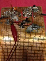
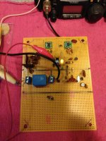
Not that pictures show much, but the latest iteration is pictured. I omitted the IF transformer and substituted a resistor load, and added the severely mismatched upc1651G as a first IF in between the two mixers to attempt to offset the gain loss. Instead of fooling with zeners, the MMIC will be powered off the 78L05 pictured, floated above ground by a diode junction. It measures out at 5.68 volts. I haven't tried this configuration yet, but it should work, the only variable should be whether or not I need to re install that transformer. Which brings up gain, gain distribution, and
AGC:
In the SG-9, a three stage IF amplifier exists, each stage being a dual gate MOSFET, so maybe 60-65 dB gain. All three stages have AGC on receive. The AGC is adequate to prevent the receiver from overloading, but the control range is limited, and it is apparent listening to it. TX output is taken after the first MOSFET, so even if it gets AGC on xmit, it won't have much gain control.
The AGC line should be compatible with the JFET mixers, but Gerhard has cautioned that whatever signal handling performance these mixers have, is compromised by AGC. I have thought that AGC action might benefit from *more* gain ahead of the IF, and would likely have put that IF stage in anyway to test this, but DF96 cautions on his page that excess gain leading to excess AGC action may lead to reduced performance. That deals with FM BCB SNR; I ran across it last summer when I was weighing whether or not I wanted to add an IF stage to that simple FM BCB tuner slapped together back then, but the general point also seems applicable here.
So, I am aware of these issues, but not really sure what, if anything, needs to, or can be, done about it. I have been thinking about it because I would like to have some ALC action in the transmitter.
Win W5JAG
The 9, 18, 36, and 54 MHz crystals that I have are the cheap stuff off eBay. The 9 MHz crystals actually had some specs, but with the others, the only spec offered was the number of crystals in the bag.
This self inflicted problem has been resolved by leaving the oscillator alone, and re installing the 36 MHz crystal.
Not that pictures show much, but the latest iteration is pictured. I omitted the IF transformer and substituted a resistor load, and added the severely mismatched upc1651G as a first IF in between the two mixers to attempt to offset the gain loss. Instead of fooling with zeners, the MMIC will be powered off the 78L05 pictured, floated above ground by a diode junction. It measures out at 5.68 volts. I haven't tried this configuration yet, but it should work, the only variable should be whether or not I need to re install that transformer. Which brings up gain, gain distribution, and
AGC:
In the SG-9, a three stage IF amplifier exists, each stage being a dual gate MOSFET, so maybe 60-65 dB gain. All three stages have AGC on receive. The AGC is adequate to prevent the receiver from overloading, but the control range is limited, and it is apparent listening to it. TX output is taken after the first MOSFET, so even if it gets AGC on xmit, it won't have much gain control.
The AGC line should be compatible with the JFET mixers, but Gerhard has cautioned that whatever signal handling performance these mixers have, is compromised by AGC. I have thought that AGC action might benefit from *more* gain ahead of the IF, and would likely have put that IF stage in anyway to test this, but DF96 cautions on his page that excess gain leading to excess AGC action may lead to reduced performance. That deals with FM BCB SNR; I ran across it last summer when I was weighing whether or not I wanted to add an IF stage to that simple FM BCB tuner slapped together back then, but the general point also seems applicable here.
So, I am aware of these issues, but not really sure what, if anything, needs to, or can be, done about it. I have been thinking about it because I would like to have some ALC action in the transmitter.
Win W5JAG
Attachments

As a general rule it is best not to apply AGC to mixers. The ideal mixing device has a square-law characteristic. Reducing gain automatically reduces the maximum signal it can handle, because you are nearer the cutoff.
The ideal AGC amplifier has an exponential characteristic (like a BJT or variable-mu valve). Reducing gain does not affect signal handling, because the curve is the same shape everywhere.
Applying the same AGC to a cascade of identical amplifiers can lead to two problems:
1. reducing gain on the first amplifier can affect S/N ratio for small signals
2. reducing gain on the last amplifier and in most cases thus restricting its possible output power can lead to it not being able to generate enough output to actually drive the AGC for large signals or at least creating significant distortion
The solution is to delay the AGC to the first amp, and reduce the AGC to the last amp. You need to get what AGC range you need mainly from the stages in the middle.
Say you had three identical stages, each potentially having 30dB AGC range. You might think you can get 90dB of AGC, but you may hit the snags I described. You may need to delay the first stage AGC so for small signals it does very little - maybe 20dB range. Then the final stage may need to have half the AGC range so that it never gets too close to cutoff. So you end up with 20+30+15=65dB AGC range, but now you get better S/N on weak signals and less distortion on strong signals. As always in design, there is a balance to be struck.
I will need to study the SG-9 schematic some more. I have assumed each MOSFET stage is getting identical AGC action, but that may or may not be true.
One of the things I have observed is that the SG-9 that I pulled from the Dentron transceiver is a little different from either schematic that I have available, so it may take board level scrutiny to be certain of just how it is distributed.
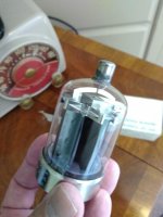
In the meantime, enough of this SMD chicanery! Look at what the mail lady just delivered - a pair of genuine NOS Tung Sol 7212's!
Just the ticket for a mobile HF amplifier ......
Win W5JAG
One of the things I have observed is that the SG-9 that I pulled from the Dentron transceiver is a little different from either schematic that I have available, so it may take board level scrutiny to be certain of just how it is distributed.
In the meantime, enough of this SMD chicanery! Look at what the mail lady just delivered - a pair of genuine NOS Tung Sol 7212's!
Just the ticket for a mobile HF amplifier ......
Win W5JAG
Attachments
If I am looking at it correctly, AGC voltage is derived from a tap near the top of the primary of the last IF XFMR, RF is sampled from the tap through a 100 pf capacitor, rectified and filtered, and a negative voltage applied to the first gate of each MOSFET; the last IF gets little to no AGC, the second stage gets the bulk of it, and the first stage gets less than the second ( middle ).
It looks like the second and third IF stages are cut off from B+ in xmit, with TX output from the 9 MHz filter going through the first MOSFET IF stage, then a JFET buffer to the outside world. So, no ALC on xmit.
If I am looking at it correctly.
Win W5JAG
It looks like the second and third IF stages are cut off from B+ in xmit, with TX output from the 9 MHz filter going through the first MOSFET IF stage, then a JFET buffer to the outside world. So, no ALC on xmit.
If I am looking at it correctly.
Win W5JAG
The talk about AGC has prompted me to take a closer look at it, and it's not working right. The documentation I can find on the Mizuho SG-9 states AGC should range from 0 to -1.5 VDC, but on this board, at a nominal 12 volts, it rests at about -0.4 VDC. It is working from the standpoint that increasing signal strength drives the AGC more negative, but not negative enough, and, as stated, it begins from the wrong point.
There is no way to adjust it, it is what it is. It uses two 1N60 germanium diodes as the rectifier, and it seems to be high by about one 1N60 diode junction, so it could be as simple as that, or that could just be a coincidence. I bought the radio this came from as a junker for parts; the brick is bad, it could have sustained other damage ( lightning?), so I probably need to go through the SG-9 board and make sure everything is working as it should.
In the meantime, the simple front end is done. The single tuned circuit at the front end should be inadequate, but it doesn't seem to be. The image is up in the FM BCB, and doesn't seem to be causing any issues. The high power shortwave stations that would overwhelm this all seem to be gone. MW breakthrough doesn't seem to be happening.
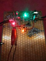
The board draws about 90 ma, probably from the MMIC and LED's. It is wired so the first mixer will get all the voltage the car electrical system can deliver, the MMIC has it's own regulator, the second LO and mixer get a regulated voltage from a 78L12, boosted by one diode juntion, about 12.6 volts. The red LED indicates power to the board, green is output from the MMIC regulator, orange the second LO/mixer regulator. They load the regulators a bit and add some pizzaz to an otherwise bleak landscape.
I couldn't get it to work satisfactorily without the IF transformer, probably because of the load of the coax pigtail. I did not try hard to solve that, since I knew a transformer would take care of it.
There is no way to adjust it, it is what it is. It uses two 1N60 germanium diodes as the rectifier, and it seems to be high by about one 1N60 diode junction, so it could be as simple as that, or that could just be a coincidence. I bought the radio this came from as a junker for parts; the brick is bad, it could have sustained other damage ( lightning?), so I probably need to go through the SG-9 board and make sure everything is working as it should.
In the meantime, the simple front end is done. The single tuned circuit at the front end should be inadequate, but it doesn't seem to be. The image is up in the FM BCB, and doesn't seem to be causing any issues. The high power shortwave stations that would overwhelm this all seem to be gone. MW breakthrough doesn't seem to be happening.
The board draws about 90 ma, probably from the MMIC and LED's. It is wired so the first mixer will get all the voltage the car electrical system can deliver, the MMIC has it's own regulator, the second LO and mixer get a regulated voltage from a 78L12, boosted by one diode juntion, about 12.6 volts. The red LED indicates power to the board, green is output from the MMIC regulator, orange the second LO/mixer regulator. They load the regulators a bit and add some pizzaz to an otherwise bleak landscape.
I couldn't get it to work satisfactorily without the IF transformer, probably because of the load of the coax pigtail. I did not try hard to solve that, since I knew a transformer would take care of it.
Attachments
As a general rule it is best not to apply AGC to mixers. The ideal mixing device has a square-law characteristic. Reducing gain automatically reduces the maximum signal it can handle, because you are nearer the cutoff.
I prefer to apply AGC before the mixer, in RF amp/preselector. For better selectivity and less of unwanted results of intermodulation. Also, application of AGC to the mixer can be reflected on the frequency of heterodyne.
The 1 uF smoothing / filter capacitor on the AGC line was bad. It tested OK out of circuit, but was not.
I replaced it and this restored normal operation. Resting voltage is now - 0.06 volts, and, using the FY6600 as an over the air test at 9 MHz, increasing signal strength would drive it to -0.6 volts, so seems to be working properly. It could be trimmed to exactly zero by adjustment of that 100 pF sampling capacitor. Normal background noise begins AGC operation, so it is sensitive enough as is.
This is the second time that I have observed a bad electrolytic capacitor to cause an excessive dc voltage on the circuit it is serving. I don't understand this failure mechanism. As a lay person, it is counter intuitive.
Win W5JAG
There are vague similarities between an electrolytic and a cell: both have metals separated by an electrolyte.
Sketchy electrolytics can cause all sorts of weird problems. Sometimes they act like caps at one frequency, but are open or inductive at another. Sometimes they can even act like crummy diodes.
This can let high frequency crud through confusing the circuit or your voltmeter. It can also create DC from RF energy. This is particularly problematic when the suspect cap is in a feedback loop like an AGC circuit.
I got a batch of 470 uF 35 V electrolytics long before the counterfeit parts issue (early 80's), but they were junk. I was trying to use them for filter caps in the power supply for a TV microwave receiver. The DC voltage was OK but there were weird noises in the TV picture or sound caused by the caps in about 10% of the units. Others had frequency drift. Replacement caps fixed the units.
This was not an oscillating regulator since there was none, but bad electros are notorious for making 78XX or LM317 regulators oscillate.
They wouldn't work for cathode bypass caps in small guitar amps either (bad sound). The only use I found for those caps were electric firecrackers!
There are vague similarities between an electrolytic and a cell: both have metals separated by an electrolyte.
Aluminium - oxide capacitors (AKA electrolytics) have conductors separated by an oxide film. They act actually as diodes between layers of an inductor, in series with capacitors.
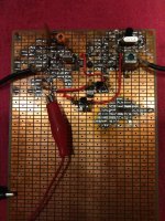
This is a double conversion setup with the HP mixers for testing. Still needs quite a bit of work.
No first IF selectivity yet.
Could need an RF preamplifier. Hard to say, yet - when driving the FT-817 as a back end, the overall noise combination of the two is misleading.
An LM375 based oscillator had no trouble driving the low impedance of the HP chip, but the simple Pierce oscillator shown here, and used on the other board, needed a buffer to be able to drive the chip. That part still needs some refinement, or I might use an LM375 here.
Not sure about optimal LO drive levels.
The TX part of the Mizhuo board seems to work, in that grounding the keying line energizes the transmitter, and putting a 1 KHz tone into the mic input yields a 9 MHz SSB supressed carrier signal, modulated at 1 KHz, at the output.
I can't start on the TX part of the transverter, because I am still undecided as to whether or not the RX will stay a double conversion up converter, or a simple single conversion down converter. The latter seems more appropriate for a simple one or two band mobile radio, but no decision has been made yet.
It occurred to me while mowing the other afternoon, that one of the 54 MHz crystals discussed above, mixed with the traditional 5 MHz LC VFO or even a VCXO, could make a clean 59 MHz tunable LO for a twenty meter up converter to 45 MHz, and get rid of that DDS whatever. So there is also that.
So no real point in working on the TX until some decisions are made.
Win W5JAG
Attachments
Here is the last weeks progress - in a nutshell, not much.
Most of my work is late at night / early morning, so not a lot of time, and most of it was wasted on just a simple buffer stage. I figured that if an MPF102 would oscillate satisfactorily at 36 MHz, it could also buffer at that frequency.
Apparently, not so. My '102's should be decent - Nat Semi and Motorola from decades ago, but I could never get one to work as a source follower buffer at 36 MHz with a waveform that I considered acceptable. After a few fruitless evenings, I switched it to a 2N3819 and got a 50 ohm output source follower with a very clean output waveform at -10 dBM for the second mixer, although the second harmonic is high at about - 26 dB. The LM375 would probably be a lot better here.
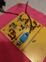
The mixers are spec'ed for a maximum +14 dBM, with best conversion gain from about -10 dBm to +5dBm. That setup with the first mixer at +13 dBm and the second at -10 dBm seemed to work pretty well, albeit not very sensitive - a total of about 14 dB conversion gain between the two. Sounded good and clean, just insensitive. I played around with a couple of MMIC's as a broadband preamp ( one can barely be seen in the photo ) and everything went to Hades in a handbag. This went from total noise, to noise plus signal, but still totally unacceptable.
I suspect the MMIC preamp and first MMIC mixer are oscillating like mad at a frequency I cannot detect as these are GHz level chips. The first mixer chip is running really hot; 50C on the case. This seems to have some relationship with the LO voltage, and to a lesser extend, VCC. In a counter intuitive manner, both mixer chips seem to run cooler with higher LO voltages.
It is in no way acceptable at present, so this will take some sorting out, probably a lot of trial and error with different combinations of LO voltage, VCC, and decoupling / better grounding. May well be a dead end, at least as a general coverage front end.
A bunch of leaded plastic J310's should arrive in today's mail, and I found a few PN4416's in my existing stash.
Win W5JAG
Most of my work is late at night / early morning, so not a lot of time, and most of it was wasted on just a simple buffer stage. I figured that if an MPF102 would oscillate satisfactorily at 36 MHz, it could also buffer at that frequency.
Apparently, not so. My '102's should be decent - Nat Semi and Motorola from decades ago, but I could never get one to work as a source follower buffer at 36 MHz with a waveform that I considered acceptable. After a few fruitless evenings, I switched it to a 2N3819 and got a 50 ohm output source follower with a very clean output waveform at -10 dBM for the second mixer, although the second harmonic is high at about - 26 dB. The LM375 would probably be a lot better here.
The mixers are spec'ed for a maximum +14 dBM, with best conversion gain from about -10 dBm to +5dBm. That setup with the first mixer at +13 dBm and the second at -10 dBm seemed to work pretty well, albeit not very sensitive - a total of about 14 dB conversion gain between the two. Sounded good and clean, just insensitive. I played around with a couple of MMIC's as a broadband preamp ( one can barely be seen in the photo ) and everything went to Hades in a handbag. This went from total noise, to noise plus signal, but still totally unacceptable.
I suspect the MMIC preamp and first MMIC mixer are oscillating like mad at a frequency I cannot detect as these are GHz level chips. The first mixer chip is running really hot; 50C on the case. This seems to have some relationship with the LO voltage, and to a lesser extend, VCC. In a counter intuitive manner, both mixer chips seem to run cooler with higher LO voltages.
It is in no way acceptable at present, so this will take some sorting out, probably a lot of trial and error with different combinations of LO voltage, VCC, and decoupling / better grounding. May well be a dead end, at least as a general coverage front end.
A bunch of leaded plastic J310's should arrive in today's mail, and I found a few PN4416's in my existing stash.
Win W5JAG
Attachments
I worked the problem for a few hours last night. I cut the first mixer off from the MMIC. I reduced the voltage to the mixers from about 7.9 ( max recommended is 8 ) to 5.8, and increased the LO drive to the first mixer to about +5 dBm. This cooled them down, and they seem stable, and working properly.
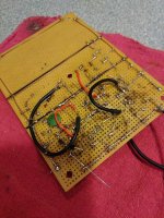
I believe the problem is isolated to the MMIC, and it is a self oscillation, as opposed to a feedback path oscillation. Even with the MMIC output physically disconnected from the first mixer input, it will still inject noise into the system if the MMIC has power applied. I suppose that could be a decoupling issue through the DC supply line, and fooled a bit with that, to no improvement. I'm using a 0.01 uF bypass at the DC supply line, but it may need a different value. Could be as simple as a grounding issue, since there is no ground plane with the perfboard. I can put my finger against the blocking input cap and quench most or all of the oscillation. I did try brute force matching the input impedance with a 47 ohm resistor on the cold side of the blocking cap, but this didn't help. The chip does not run hot , the case is cold to the touch. I could cut the voltage back to maybe stop it, but this would kill the noise figure, so not an acceptable solution other than for testing / diagnosis purposes.
Apparently these unconditionally stable devices can be made unstable. This new knowledge comes at an inconvenient time.
Win W5JAG
edit: the first LO coax is laying right on top of the MMIC. It is shielded, the shield grounded at the opposite side from the mixer. Could RF be leaking out into the MMIC? Could it be as simple as just rerouting that cable?
Last edited:
- Home
- Member Areas
- The Lounge
- No RF gear here?