The title should be changed to "CFA or No NFB line amp (GainWire mk2)".another fine amp circuit and performance from you.....
It seems most of the happy builder of this fine preamp prefer CFA mode. I wonder why (while I'm not surprised, as Wally already knows ;-)
another fine amp circuit and performance from you..... 😎🙂
THx-RNMarsh
Thank you Richard, somewhere on your workbench is forgotten this preamp PCB.
BR Damir
The title should be changed to "CFA or No NFB line amp (GainWire mk2)".
It seems most of the happy builder of this fine preamp prefer CFA mode. I wonder why (while I'm not surprised, as Wally already knows ;-)
When I started with this preamp design, the idea was non NFB as a current conveyor is good choice to start with. Latter it came a CFA as good alternative.
This said, i would be really interested to understand why this difference i noticed so often.When I started with this preamp design, the idea was non NFB as a current conveyor is good choice to start with. Latter it came a CFA as good alternative.
I made a lot of comparisons in my life between VFA and CFA with the same global designs. Always preferred CFAs during listening sessions.
But I never did this with non NFB.
On an intellectual point of view, this result is surprising (at least for the objectivist troop here). With so low distortion numbers, in both modes, I believe nothing is to be found in this direction. As with no GFB, no TIM to fear, and no stability issue, nothing there too. And nothing in correlation with speaker's drive, here. So, what ?
The difference is clearly to be found in the "Expansive VS Compressive" dynamic behavior.
BTW: I will use your design, I think, to modify two Koss ESP9 electrostatic headphone energizers in order to drive directly the phones from line signals.
I hope it will be able to afford their internal caps.
Last edited:
dadod, I will need a X10 gain, and 10V max in output. Could-you lead-me to your last ASC file, for i can simulate how it will behave in such conditions ? Thank in advance.
(it should be good to update your first post with them, don't you think ?)
(it should be good to update your first post with them, don't you think ?)
dadod, I will need a X10 gain, and 10V max in output. Could-you lead-me to your last ASC file, for i can simulate how it will behave in such conditions ? Thank in advance.
(it should be good to update your first post with them, don't you think ?)
Esperado, here is zip file with .asc and Cordell models.
I will update the first post when I get more time.
Attachments
I have been listening to this preamp for a while now and truly prefer No GNF.
Feedback seems to limit high freq detail and also image size and depth.
Feedback seems to limit high freq detail and also image size and depth.
Thanks a lot, dadod. Fascinating amp. And a lot to play with.Esperado, here is zip file with .asc and Cordell models.
Could-you explain your compensation scheme ?
Interesting opinion.I have been listening to this preamp for a while now and truly prefer No GNF.
Feedback seems to limit high freq detail and also image size and depth.
Could-you be more talkative ? What character was more pleasant at the first listening sessions with CFA that you preferred ? Is the difference obvious, or that kind of difference we are never sure about and need several comparisons ?
Last edited:
Thanks a lot, dadod. Fascinating amp. And a lot to play with.
Could-you explain your compensation scheme ?
The CFA gain is defined as R12/(R19//R9)+1
NGNFB gain is defined as R11/R9
Shunt compensation is R39, C2. For more gain set you can decrease C2 and increase R39.
Just play with it and check distortion for different feedback leg impedance.
That i had done in the first 5 seconds of my sims, of course.The CFA gain is defined as R12/(R19//R9)+1
NGNFB gain is defined as R11/R9
Shunt compensation is R39, C2. For more gain set you can decrease C2 and increase R39.
Just play with it and check distortion for different feedback leg impedance.
My question was not clear: Why did-you chose this kind (shunt) of compensation ?
As this amp has to be stable in both mode, the shunt compensation is simplest and best way. Do not thing that NGNFB could not oscillate!That i had done in the first 5 seconds of my sims, of course.
My question was not clear: Why did-you chose this kind (shunt) of compensation ?
I had designed some oscillators (and amps): Don't worry, Murphy was always on my side.Do not thing that NGNFB could not oscillate!
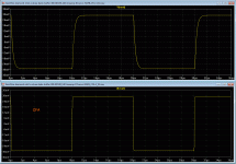
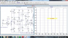
No way to get clean little signal fast square waves in CFA.
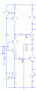
I believe your input stage have to be dumped (as expected). I have added base stoppers to the second stage. (100 Ohms )
I believe your input stage have to be dumped (as expected). I have added base stoppers to the second stage. (100 Ohms )
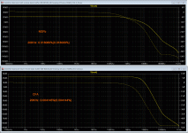
The response curves (Rails +/-18V, Vout 11.6V. Distortion at 1KHz= 0):
Attachments
Last edited:
No way to get clean little signal fast square waves in CFA.
I believe your input stage have to be dumped (as expected). I have added base stoppers to the second stage. (100 Ohms )
............
Still a point to fix: the catastrophic clipping behavior.
Sorry to say this Esperado, but you are doing something wrong here.
In the gain versions of 7x and 3.5x I showed, the square waves are very clean with no overshoot and no need for base stoppers (as expected). You can find all this simulations in this thread.
Catastrophic clipping behavior, you like strong words. When this pream start to clip it is very benign. Why do you need to push it in heavy clipping? If you need more output voltage use higher voltage power supply. With +-15 V this preamp start to clip at 12 V of peak output voltage and that was perfectly adequate for what was designed, line and phone amp. Why someone would push the preamp in so heavy clipping if the power amp will start to clip long before, or you will destroy your hearing with the headphones before it start to clip.
Maybe you can start your own thread with your specific requirement for the preamp.
Maybe you can start your own thread
I don't think so. I don't.Sorry to say this Esperado, but you are doing something wrong here.
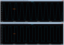
Oh, please, don't be on the defensive, dadod. Your preamp is fantastic/amazing. Look at my results at > 10V with > 23dB of gain !!!!
Let me explain my purpose. I intent to use this as an amplifier for an electrostatic headphone (Koss ESP-9). It needs, at the origin, an amplifier of 12W. In other words, 10Veff. Reason why there is, contrary at the situation of an ordinary preamp that will never reach this point, clipping behavior on the road. And, about "strong words", there were a little pinch of second degree in-it (I hate emoticons or smileys): Who want to reach the clipping point, we are supposed to build HIFI systems, no ?
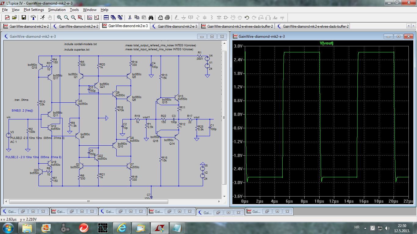
On the subject of square waves, there were one of your sims:
diyAudio
Notice that your track was not the same than mine: you worked with a NGFB , while i am optimizing-it in its CFA mode witch is faster and more prone to overshoots.
I used "Diamonds" or "Super pairs" long before names were put on those assemblies. And designed several industrial products with them since 1970. I always found-them "nervous". Here again. And, as those base stoppers killed the problem, with no major impact on the distortion, what the hell ? I supposed you will be happy to look at this as a contribution. Notice I did exactly the same thing than here:
www.esperado.fr - VSSA with Diamond input and DC servo
And that this offer several advantages. Clean square waves, extended bandwidth, isolation of the input low pass filter from influence of impedance of the source, as in my sim where your input pass filter was removed. In the VSSA Diamond, the positive influence of this filter was obvious in listening. And I expect the same here.
Attachments
Last edited:
nb: in my sim, the compensation cap was reduced to 50pF witch extend smootly the bandwidth at HF, as you had seen, with no more this brutal (smiley here) phase shift at 100MHz.
I don't think so. I don't.
Oh, please, don't be on the defensive, dadod. Your preamp is fantastic/amazing. Look at my results at > 10V with > 23dB of gain !!!!
Let me explain my purpose. I intent to use this as an amplifier for an electrostatic headphone (Koss ESP-9). It needs, at the origin, an amplifier of 12W. In other words, 10Veff. Reason why there is, contrary at the situation of an ordinary preamp that will never reach this point, clipping behavior on the road. And, about "strong words", there were a little pinch of second degree in-it (I hate emoticons or smileys): Who want to reach the clipping point, we are supposed to build HIFI systems, no ?
On the subject of square waves, there were one of your sims:
diyAudio
Notice that your track was not the same than mine: you worked with a NGFB , while i am optimizing-it in its CFA mode witch is faster and more prone to overshoots.
I used "Diamonds" or "Super pairs" long before names were put on those assemblies. And designed several industrial products with them since 1970. I always found-them "nervous". Here again. And, as those base stoppers killed the problem, with no major impact on the distortion, what the hell ? I supposed you will be happy to look at this as a contribution. Notice I did exactly the same thing than here:
www.esperado.fr - VSSA with Diamond input and DC servo
And that this offer several advantages. Clean square waves, extended bandwidth, isolation of the input low pass filter from influence of impedance of the source, as in my sim where your input pass filter was removed. In the VSSA Diamond, the positive influence of this filter was obvious in listening. And I expect the same here.
Here is square wave simulation with input filter removed, no nervousness here. I think that you are a bit nervous about it not the circuit. I used similar input configuration in my CFA VMOSFET power amp with no problem, stable as a rock. Some overshoots on the square wave simulation is nothing so bad to worry about it.
I know about your suggestion where to put LP filter, it has a advantage to be not sensitive to the source impedance, but has disadvantage as it requires two precise resistor and two precise capacitors.
By the way in your attached IPS schematic there is missing connection between Q11, Q12 collector and the feedback input.
Attachments
- Status
- Not open for further replies.
- Home
- Amplifiers
- Solid State
- No NFB line amp (GainWire mk2)