Will do
Thank you Pawel and dadod.
Now I remenbered you used the same fet to create Vref in both pos and neg lines.... hope I got a good combination of resistor values so voltage is equal both rails 🙂
Thank you Pawel and dadod.
Now I remenbered you used the same fet to create Vref in both pos and neg lines.... hope I got a good combination of resistor values so voltage is equal both rails 🙂
small erratum:
from the parameters I can see that the pair IRF640/9540 is better compatible.
Would you post here the values/parameters that you are referring to ?
Rds(on) ?
Gfs ?
Capacitance values ?
transistor Rdson Cin Cout
IRF640 0.18 1300 430
IRF9540 0.20 1400 590
for Gfs please check their datasheets
IRF640 0.18 1300 430
IRF9540 0.20 1400 590
for Gfs please check their datasheets
Last edited:
Allready have all the parts
One doubt arises.... Can I bolt the mosfet pairs together into the heatsinks without caring about isolation ?
One doubt arises.... Can I bolt the mosfet pairs together into the heatsinks without caring about isolation ?
The shunts work flawlessly..... congrats dadod 🙂
Next step... connect the amps without the servos....
A blast as always 🙂
Next step... connect the amps without the servos....
A blast as always 🙂
Nice, clean and stable squares and sinuses it produces in my scope.... now building the case with proper connections so I can finally listen to it 🙂
Nice, clean and stable squares and sinuses it produces in my scope.... now building the case with proper connections so I can finally listen to it 🙂
Waiting for your listening opinion.
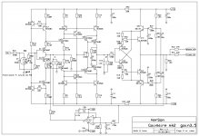
There is a difference between the schematic and the board layout in the input.
Resistor R29 (47k) is connected between gnd and Q11 Q12 bases.
So P1 from the pot only connects directly to R50 (1k) and not to R29.
it seems ok to me but am I right ?
Resistor R29 (47k) is connected between gnd and Q11 Q12 bases.
So P1 from the pot only connects directly to R50 (1k) and not to R29.
it seems ok to me but am I right ?
I have static (DC) offset in the input.
I did not connect the 10k yet so I am measuring input offset at P1 (just before the 1k R50)
I read 11mV..... should I expect a reduction of this value when I connect the pot ?
IMO it is the Q11 Q12 base current flowing in the 47k to gnd, so paralleling the 10k pot should reduce the offset right ?
I did not connect the 10k yet so I am measuring input offset at P1 (just before the 1k R50)
I read 11mV..... should I expect a reduction of this value when I connect the pot ?
IMO it is the Q11 Q12 base current flowing in the 47k to gnd, so paralleling the 10k pot should reduce the offset right ?
Last edited:
I just used alligator clips to connect the pot and offset got down to a confortable 1.7mV... cool
There is a difference between the schematic and the board layout in the input.
Resistor R29 (47k) is connected between gnd and Q11 Q12 bases.
So P1 from the pot only connects directly to R50 (1k) and not to R29.
it seems ok to me but am I right ?
Yes you are correct. I changed that on the layout but forgot to do that on the schematic. This does not change anything functionally.
Attached is corrected schematic.
Attachments
I do not have any 220p for C7.... can I use 150p or should I go to 270p ?
This is input LP filter not critical. Use 150p.
I just used alligator clips to connect the pot and offset got down to a confortable 1.7mV... cool
This offset is coming from not perfect matching of the input transistors, but important is output DC offset controlled with the DC servo.
About TIM, i believe this filter is not critical when using no NFB. I should try the best value in careful listening when global feedback is used. It can change a lot the sound quality depending of the other components in your system, specially the power amps. Sometimes, drastic filtering gives the best results.This is input LP filter not critical. Use 150p.
About TIM, i believe this filter is not critical when using no NFB. I should try the best value in careful listening when global feedback is used. It can change a lot the sound quality depending of the other components in your system, specially the power amps. Sometimes, drastic filtering gives the best results.
This a bit tricky, you should take in account the source impedance, and off course the power amp input LF filter. When you say drastic filtering, you don't thing that we have to go below 20kHz? And depends what the source is, analog or digital? Many variables here.
Indeed, dadod.This a bit tricky, you should take in account the source impedance, and off course the power amp input LF filter. When you say drastic filtering, you don't thing that we have to go below 20kHz? And depends what the source is, analog or digital? Many variables here.
Well, my CFA power amp use Diamond input, now. Its LF filter is isolated between the two emitter followers. Set just enough to avoid overshoot on little signal square waves (MHz) while compensated for flat bandwidth with no peak at HF.
This gives-me the widest bandwidth i can hold without any fear to see signals faster than its slew rate creating TIM. Independant from the source impedance. And remove something that i don't like in the diamond... some kind of a "nervous" character ;-)
In my situation, i should do the same for the pre-amplifier.
Now, somewhere in the channel, as close as the source as possible, i like to try to decrease the upper frequency of the all system. It depends a lot of the speakers we use, the source's quality etc, tricky as you said.
I do-it by a careful listening, in a very subjective way. "Voicing" ;-)
Of course i don't think reducing 20KHz signals in levels. Phases are a concern too. But sometimes, it can help ?
I was never able to add a super tweeter to my speakers with natural results. It is a two ways, using spherical horns for the high-medium. It cuts somewhere near 16KHz. Any try to increase the bandwidth at the upper frequencies (even with my active filter) seems just to add distortions and false trebles.
Last edited:
- Status
- Not open for further replies.
- Home
- Amplifiers
- Solid State
- No NFB line amp (GainWire mk2)