Done. I move R11 to R12 and use two 1K parallel for 500 ohmsSo I can continue my quest without waiting for just two resistor.
Tell about your listening impression. I hope you did not use that 500R combination in R12 position, it quite important to have 470R there.
Tell about your listening impression. I hope you did not use that 500R combination in R12 position, it quite important to have 470R there.
I did the right thing: 470R for R12 and 2x1K for R11. Both channels are working fine now.
I will tell more about my listening impression when I complete the next power amp project when it act like a pre-amp.
Regards the buzz problem, the buzz increase when I touched the input and goes away when I shorted the input. Is this normal?
Last edited:
I did the right thing: 470R for R12 and 2x1K for R11. Both channels are working fine now.
I will tell more about my listening impression when I complete the next power amp project when it act like an pre-amp.
Regards the buzz problem, the buzz increase when I touched the input and goes away when I shorted the input. Is this normal?
If the buzz goes out when the input shorted that shows buzz is coming outside the preamp, probably electromagnetic interference(transformer?).
If the buzz goes out when the input shorted that shows buzz is coming outside the preamp, probably electromagnetic interference(transformer?).
So at least the preamp is ok. I will try to detect this problem. May be try with another transformer ...
So at least the preamp is ok. I will try to detect this problem. May be try with another transformer ...
When test, I short P1-P2, make P1-G nothing. Signal come from IN. Could it be the problem of buzz sound?
When test, I short P1-P2, make P1-G nothing. Signal come from IN. Could it be the problem of buzz sound?
Could you be more specific, I really don't see what you trying to say, show on the schematic. I mean the connection of the source.
Could you be more specific, I really don't see what you trying to say, show on the schematic. I mean the connection of the source.
Sorry for not being clear about it. Here is the input diagram:
Attachments
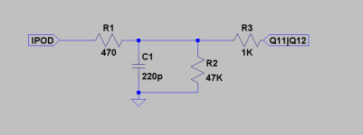
Sorry for not being clear about it. Here is the input diagram:
I have to say sorry. I mean what's going on when you said "I short P1-P2, make P1-G nothing. Signal come from IN"? When there is no buzz?
I have to say sorry. I mean what's going on when you said "I short P1-P2, make P1-G nothing. Signal come from IN"? When there is no buzz?
I mean I setuped like this schematic when I did my test. When no source connected, the are some buzz (small level) on the headphone. BUT when connect the source or short input to ground, the buzz sound gone away, totally silent. Do you think do casing then connect ground point to chassis will solve this problem?
I mean I setuped like this schematic when I did my test. When no source connected, the are some buzz (small level) on the headphone. BUT when connect the source or short input to ground, the buzz sound gone away, totally silent. Do you think do casing then connect ground point to chassis will solve this problem?
When you put your input attenuator to the lowest level does the buzz disappear?
When you sa short to ground, do you mean to the PCB ground. Do you have intention to connect mains ground to the chassis? If yes, than you have to use A High Current Safety Loop Breaker Circuit as in figure 4. here: Earthing (Grounding) Your Hi-Fi - Tricks and Techniques
I have no input attenuator, I used ipod to control the volume. I only short input to PCB ground. I will buy a chassis later and try that.
My country AC doesn't have the earth rail. Will my setup will be different?
My country AC doesn't have the earth rail. Will my setup will be different?
I have no input attenuator, I used ipod to control the volume. I only short input to PCB ground. I will buy a chassis later and try that.
My country AC doesn't have the earth rail. Will my setup will be different?
I think that this preamp deserves something better than ipod.
So you say that a mains socket does not have third earth connector?
When the preamp input is not connected anywhere the input impedance is of 47k and if you have a transformer or some stray magnetic field in proximity than is possible to have a buzz.
Yes, my main socket have two connectors so no earth connector.
I agree that the preamp deserves something better than my old ipod nano g1 but that ipod let me test something easier.
I think I got my problem. I didn't have an input attenuator so input impedance will be 47k when source not connect. If I add an input attenuator, it will much lower ( < 10K // 47K) and the problem will gone (or lower). I think I will go ahead and just finish the pre-amp.
Last edited:
If I'm not completely wrong you need the input ground to install a proper grounding scheme. Then the noise is lowered by a huge margin.
Best regards,
Matthias
Best regards,
Matthias
Hi dadod
Finally got all the parts and time to start this project.
As usual I like to sim the schematics I am building so I can verify voltages and currents in the real build.
I started with the 3.5gain version and everything seems normal with J1 and J2 junpers in place but if I remove them, gain is so high that the output is always clipped.
Please have a look at this sim and let me know what is going wrong.
Attachments
Hi dadod
Finally got all the parts and time to start this project.
As usual I like to sim the schematics I am building so I can verify voltages and currents in the real build.
I started with the 3.5gain version and everything seems normal with J1 and J2 junpers in place but if I remove them, gain is so high that the output is always clipped.
Please have a look at this sim and let me know what is going wrong.
You probably forgot that, but it was described earlier in this thread. Never put both jumpers or remove both jumpers. For CFA mode put J1 jumper only and for NGNFG put J2 jumper only.
Thank you so much dadod
You are really kind.
I just reread the whole thread today and obviously missed that important part.
You are really kind.
I just reread the whole thread today and obviously missed that important part.
Thank you so much dadod
You are really kind.
I just reread the whole thread today and obviously missed that important part.
You re welcome, when you finish the GainWire tell your impression.
A few words sometimes makes things a lot easier.
Now I see clearly that J1 enables NFB. If we cut NFB, gain will rise and we must reduce it by using J2.
If J2 can be tweaked to lower gain, why not use it as volume control ?
Now I see clearly that J1 enables NFB. If we cut NFB, gain will rise and we must reduce it by using J2.
If J2 can be tweaked to lower gain, why not use it as volume control ?
A few words sometimes makes things a lot easier.
Now I see clearly that J1 enables NFB. If we cut NFB, gain will rise and we must reduce it by using J2.
If J2 can be tweaked to lower gain, why not use it as volume control ?
I think that I mentioned that in this thread, I am not sure. Yes it is possible to make R17 a volume attenuator, let say if you use 2k potentiometer instead R17, but remember this is possible only in NGNFB only, so forget CFA part. There is not easy to find good quality 2k log pot or stepped volume attenuator.
- Status
- Not open for further replies.
- Home
- Amplifiers
- Solid State
- No NFB line amp (GainWire mk2)