Hi, I need some help on the preamp. What is the prefer capacitor type C7 and C2 rather C0G/NP0?
Hi, I need some help on the preamp. What is the prefer capacitor type C7 and C2 rather C0G/NP0?
You can use ceramic C0G/N0P, or polystyrene, or silver mica, or even polypropylene.
You can use ceramic C0G/N0P, or polystyrene, or silver mica, or even polypropylene.
Thanks! I will use C0G/N0P caps which are in my hand now.
One more thing, Q23 and Q24 are BD139/BD140, which brand is prefer for those device, OnSemi, ST or Fairchild? Do they need some kind of matching?
Thanks! I will use C0G/N0P caps which are in my hand now.
One more thing, Q23 and Q24 are BD139/BD140, which brand is prefer for those device, OnSemi, ST or Fairchild? Do they need some kind of matching?
Any of those brands will be good, no matching needed, just small heat sink on each one.
I'm nearly finish one channel of the pre-amp, only R30, R31 left. I don't have 180R for them. But I do have 200R, 221R and org 270R. Which one should I use? Any change in perfomance?
I use gain 3.5x setting.
I use gain 3.5x setting.
I'm nearly finish one channel of the pre-amp, only R30, R31 left. I don't have 180R for them. But I do have 200R, 221R and org 270R. Which one should I use? Any change in perfomance?
I use gain 3.5x setting.
Higher those resistors more current though output transistors. I originally used 270R in those positions, but with my small heat sink on Q23, Q24 they get a bit to hot. Try with 200R, if you want to use low impedance headphones you can try 221R or even 270R. Check the temperature of Q23, Q24.
The gain setting does not have anything with those resistors.
When you do listening, please report back your impression.
When you do listening, please report back your impression.
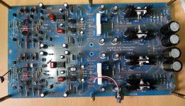
I finished one channel of the pre-amp, after some problem with the PSU (I swapped 10R / 100R and it cause too much voltage drop on negative channel). Other channel will be wait for missing component (I bought them but lost them now). This is the first DIY project to me.
My gain is: 3.5x
R30, R31 = 221 Ohms
All small caps are 220pf
I didn't have fancy equipment or headphone. My test equipment are:
Source: HiFimeDIY Sabre v2
Headphone: KRK KNS6400
When testing. I thinked Gainwire mkII is quite nature in sound. CFA make sound a litle grainier, NOGFB make sound a bit more sweet. I need to test more and decide which mode will suit me better. And it is sound good to me, much better than some CMOYs, low voltage tube headphone amp which I used before.
One problem, when no source connect, I hear a little buzz in my headphone but it gone when connect any source. Is it some kind of problem?
And I'm interested with a SMD version of the preamp, too.
Attachments
Last edited:
I finished one channel of the pre-amp, after some problem with the PSU (I swapped 10R / 100R and it cause too much voltage drop on negative channel). Other channel will be wait for missing component (I bought them but lost them now). This is the first DIY project to me.
My gain is: 3.5x
R30, R31 = 221 Ohms
All small caps are 220pf
I didn't have fancy equipment or headphone. My test equipment are:
Source: HiFimeDIY Sabre v2
Headphone: KRK KNS6400
When testing. I thinked Gainwire mkII is quite nature in sound. CFA make sound a litle grainier, NOGFB make sound a bit more sweet. I need to test more and decide which mode will suit me better. And it is sound good to me, much better than some CMOYs, low voltage tube headphone amp which I used before.
One problem, when no source connect, I hear a little buzz in my headphone but it gone when connect any source. Is it some kind of problem?
And I'm interested with a SMD version of the preamp, too.
I am glad that you like the sound. You have nice board there, have you made the layout looking to my layout? Excellent for first DIY project.
Regarding the buzz it could be a grounding problem, I have no buzz source connected or not.
I would like to make a SMD version, but that is a new field for me and I need time for that.
Damir
Yes, I made them when looking at your board, it is the same layout as yours but using my specific component footprint. I wish I could order the board from you but I got bad experience with my country shipping service.
About the buzz, when no source connected, the voltage between input + and - is 16mV, is it because of mismatch of the bjt vbe? The output DC is 0.1mV.
Probably, and DC servo corrects output offset. Try with no opamp and see the dc offset.
Probably, and DC servo corrects output offset. Try with no opamp and see the dc offset.
Are the two missing 470R on another channel can cause any damage when I power the preamp? May be I need to wait and finish the another channel before doing more work on it.
Are the two missing 470R on another channel can cause any damage when I power the preamp? May be I need to wait and finish the another channel before doing more work on it.
It's that R12 in? You can try both channels in NOGNFB if only those resistors are missing.
It's that R12 in? You can try both channels in NOGNFB if only those resistors are missing.
They are R12 and R19 on one channel. Is it still ok?
They are R12 and R19 on one channel. Is it still ok?
But R19 is 330R? If that than you can play in NOGNFB in both channels.
But R19 is 330R? If that than you can play in NOGNFB in both channels.
Sorry, it is R11 which right after the NOGNFB jumper. I think it is still ok?
Sorry, it is R11 which right after the NOGNFB jumper. I think it is still ok?
That one you need, but the value is not critical, use anything close as 420R or 330R or 560R but in both channels.
That one you need, but the value is not critical, use anything close as 420R or 330R or 560R but in both channels.
Ok. Then I just need to get that 470R from working channel R12 and have both work on NOGFB mode.
Ok. Then I just need to get that 470R from working channel R12 and have both work on NOGFB mode.
If you mean R12, yes.
If you mean R12, yes.
Done. I move R11 to R12 and use two 1K parallel for 500 ohms
 So I can continue my quest without waiting for just two resistor.
- Status
- Not open for further replies.
- Home
- Amplifiers
- Solid State
- No NFB line amp (GainWire mk2)