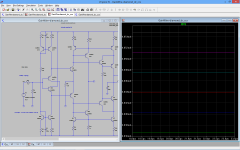
I have made a temperature sweep from 0º to 50º and the alteration have manage to compensate the temp. variation, except for the input stage, 13mv.
ofcourse a sub mv variation is only possible with a dc-servo.
You should also check the ccs at input, the bias current changed from 4.5ma to 3.8ma with the temp. variation, I recomend another type of ccs.
What kind CCS do you recomend?
This one is good enough , only 18uA variation in 50º .
I like that CCS type, kind of CM-CCS.
I did some more simulation and this is what I've found.
This one has bigger current fluctuation provoked by audio signal or power voltage change then BJT-BJT feedback type but better thermal stability and less temperature dependent distortion.
Does it need two more electrolytic caps? Without them distortion is a bit lower.
BR Damir
Last edited:
"This one has bigger current fluctuation provoked by audio signal or power voltage change then BJT-BJT feedback type but better thermal stability and less temperature dependent distortion."
The higher current fluctuation provoked by audio signal, is because the output impedance is lower than the ccs with feedback , but it is better than 500K ohms , so I think is enought for this aplication, the impedance can be increase a lot , by cascode bootstrapping the output transistor , but I think the added complexity is not need here.
"Does it need two more electrolytic caps? Without them distortion is a bit lower."
The electrolytic caps reduce the noise . And increase the output impedance a bit.
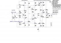
Some times I use this one also, It has the same output impedance, but as it uses a reference voltage I.C. the output current is the same with a higher range of supply voltages, I normaly use tl431 in U1, U2 . (R1/C5) (R2/C6) are important to keep the output noise very low, without this filters, the noise of the Tl431 is a bit higher , one can use lower noise references than the tl431, but I find out, that is no need.
The higher current fluctuation provoked by audio signal, is because the output impedance is lower than the ccs with feedback , but it is better than 500K ohms , so I think is enought for this aplication, the impedance can be increase a lot , by cascode bootstrapping the output transistor , but I think the added complexity is not need here.
"Does it need two more electrolytic caps? Without them distortion is a bit lower."
The electrolytic caps reduce the noise . And increase the output impedance a bit.
Some times I use this one also, It has the same output impedance, but as it uses a reference voltage I.C. the output current is the same with a higher range of supply voltages, I normaly use tl431 in U1, U2 . (R1/C5) (R2/C6) are important to keep the output noise very low, without this filters, the noise of the Tl431 is a bit higher , one can use lower noise references than the tl431, but I find out, that is no need.
Attachments

Last edited:
"This one has bigger current fluctuation provoked by audio signal or power voltage change then BJT-BJT feedback type but better thermal stability and less temperature dependent distortion."
The higher current fluctuation provoked by audio signal, is because the output impedance is lower than the ccs with feedback , but it is better than 500K ohms , so I think is enought for this aplication, the impedance can be increase a lot , by cascode bootstrapping the output transistor , but I think the added complexity is not need here.
"Does it need two more electrolytic caps? Without them distortion is a bit lower."
The electrolytic caps reduce the noise . And increase the output impedance a bit.
Some times I use this one also, It has the same output impedance, but as it uses a reference voltage I.C. the output current is the same with a higher range of supply voltages, I normaly use tl431 in U1, U2 . (R1/C5) (R2/C6) are important to keep the output noise very low, without this filters, the noise of the Tl431 is a bit higher , one can use lower noise references than the tl431, but I find out, that is no need.
Thanks for explanation,
In the simulation adding electrolytic caps does not change significantly the noise level. CMs are with high enough emmiter resistors to have quite low noise.
BR Damir
Noise from the power supply, if you feel that your power supply is quiet enough , you can skip the caps.
Would you be kind enough to share your spice models (e.g. post #154, #162)?
Thanks in advance,
Patrick
Thanks in advance,
Patrick
Noise from the power supply, if you feel that your power supply is quiet enough , you can skip the caps.
You mean PSRR?
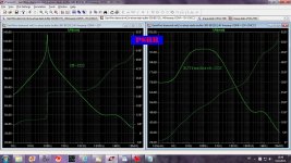
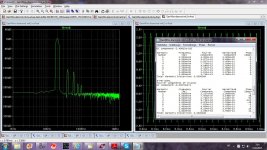
Here is difference between CM-CCS and BJT feedback CCS(no caps in CM, caps do not improve significantly)) and there is not big difference, good enough both of them.
This pure GainWire with no power filtering and no ODNF.
BR Damir
Sorry the graph should be interchanged.
Attachments

Last edited:
Would you be kind enough to share your spice models (e.g. post #154, #162)?
Thanks in advance,
Patrick
Hi Patrick ,
the spice models were created by bob cordell , and they are avaiable in Bob cordell home page , in post #85 Damir has post a zip file that also contains the models.
"Here is difference between CM-CCS and BJT feedback CCS(no caps in CM, caps do not improve significantly)) and there is not big difference, good enough both of them."
So , there is no reason to use the capacitors 🙂
Very good.
So , there is no reason to use the capacitors 🙂
Very good.
I decided to change CCS type as the CM-CCS has simple posibility to adjust the current by changing just one resistor and it is not inferior to the BJR feedback type.
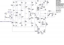
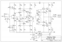
Here are new schematics one with ODNF and other with DC servo. PCB could be used for three configurations, NOGFB, ODNF and DC servo. In case of NOGFB and DC servo P3 could be used as volume control.
NOGFB - J1 jumper connected,
not used U1 R38, R12, R36 ,P2 D1, D2, C9 and C10
DC servo - J3 and J4 jumpers, U1, D1, D2, R38, C12, C9 and C10,
not used R12, R36, P2
ODNF - J2 jumper, U1, R38, R12, R36, C9 and C10
not used D1, D2 and C12
BR Damir
Attachments
![GainWire-mk2-32_300-ODNF-c.LAY].jpg](/community/data/attachments/351/351014-b8a1a526b6b42c3a94405417f54cb78d.jpg?hash=uKGlJra0LD)
Damir is it final version ?? If you order PCBs Im interested.
I hope it's final, and I would like to make prototype first, but not before 15th of September as I am going two weeks to an island for summer vacation.
If someone is ready to try first, PCB pdf is in previous post.
BR Damir
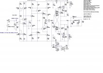
Before I go for vacation I would like to show NGNF line preamp with very low distortion.
P1 could be used as volume conntrol(fixed signal/noise ratio), or use clasical input volume control. P2 to be used to set zero DC at the output(could comprises combination of paralled fixed resistor and trimer).
BR Damir
P1 could be used as volume conntrol(fixed signal/noise ratio), or use clasical input volume control. P2 to be used to set zero DC at the output(could comprises combination of paralled fixed resistor and trimer).
BR Damir
Attachments
![GainWire-mk2-32_300-e.LAY].jpg](/community/data/attachments/334/334846-216bce7a49f10f6ae2a22844eaf97cbb.jpg?hash=IWvOeknxD2)
On the preamp, you mirror the current into the input stage, then it will be quite easy to servo it.
On the preamp, you mirror the current into the input stage, then it will be quite easy to servo it.
Sorry I don't understand what you mean, could you elaborate?
You forget to put a resistor between q18 and q20.
The collector of q15 is not connected in the right place.
The collector of q15 is not connected in the right place.
Last edited:
You forget to put a resistor between q18 and q20.
The collector of q15 is not connected in the right place.
Oh yes, you've got a good eye, if you can check the PCB could be very nice. I always make similar stupid mistakes.
Attachments

- Status
- Not open for further replies.
- Home
- Amplifiers
- Solid State
- No NFB line amp (GainWire mk2)