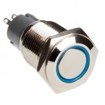
I use this.
I think that the led inside is for 12v.(led+resistor).
When first time testing,i used a discrete led.
I will try again with the discrete.
I think that the led inside is for 12v.(led+resistor).
When first time testing,i used a discrete led.
I will try again with the discrete.
Attachments
Last edited:
I used a similar one, it has 5 connections on the rear.
took a bit of experimenting to get the right wiring, but the result was a dim light on standby and brighter when on
took a bit of experimenting to get the right wiring, but the result was a dim light on standby and brighter when on
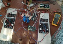
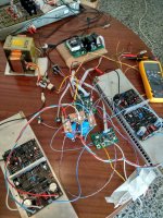
Mistery solved!
There are 3 different situations.
OFF=the lowest luminosity.
ON at delay time=a little brighter.
Delay time passed=full luminosity.😉
In my previus test i haven't the rails connected so system don't passed to real ON.(FLASHING LED).
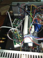
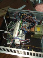
Here is the full setup.
There are 3 different situations.
OFF=the lowest luminosity.
ON at delay time=a little brighter.
Delay time passed=full luminosity.😉
In my previus test i haven't the rails connected so system don't passed to real ON.(FLASHING LED).
Here is the full setup.
Attachments
Last edited:
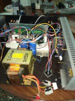
I have test the d.c protection and the fast A.C remove and place again.
I will test the temperature sensors latter.
Just a question.
How the system act if one rail, positive or negative will be absent?
I will test the temperature sensors latter.
Just a question.
How the system act if one rail, positive or negative will be absent?
Yes this is obvious,i will ask different...there isn't a power loss circuit in this protection when
other speaker protection systems have a such circuit.
Why? 😕
PS no need because this protection act instandly when power shut down?
other speaker protection systems have a such circuit.
Why? 😕
PS no need because this protection act instandly when power shut down?
Last edited:
This is a different than a simple speaker protection system. In normal operation the voltage loss detection circuit doesn't need to shut off the speaker relay, the microcontroller does this. If the DC detection circuit activates due to power loss it does instantly disconnect the speaker relay as a redundant protection at the same time as it signals problems to the microcontroller though.
Ok.
How easy is to mofify the code for the stand by led?
Will be beautiful to slowly fade in-fade out led in the stand by mode. 😉
How easy is to mofify the code for the stand by led?
Will be beautiful to slowly fade in-fade out led in the stand by mode. 😉
Last edited:
The LED is connected to pin D4 which unfortunately is a digital pin only, no analog write/PWM available on it.
Understand.
A second cheap arduino that take this digital port as a trigger to do the job?
Is it possible or i say.....
A second cheap arduino that take this digital port as a trigger to do the job?
Is it possible or i say.....
Last edited:
You could jumper the led to another pin. There should be some pwm pins available on the ICSP port.
I'll try to put some software together this weekend. All of the latest versions of the control boards already have the LED connected to PWM pins so the standby mode brightness can easily be adjusted in software.
Simpelstark wit 21"century speaker protection .
21 " Century speaker protection, Simpelstark. - YouTube
21 " Century speaker protection, Simpelstark. - YouTube

From whatever I could hear on youtube it sounds very nice and feels more natural and free.Another one with Greek Music.
Fane 12-250TC on Simpelstark. Stereo - YouTube
- Home
- Amplifiers
- Solid State
- No-global-loop amplification