Something has subconiously been gnawing at me.. i think my pnp is the wron he way on the previous shunt too (from visual memory).
I've been trying to think through the current loops for both DC and HF (both incoming and generated on the power line by the oscillator etc):

I'll continue with this - my understanding of the waveform front ie the dI/dt change as the power rail pulls current may be incorrect but I based it on this:
First a beginner introduction
The difference between DC and HF (10kHz up) is demonstrated here:
This one is on my to watch list too:
I'll continue with this - my understanding of the waveform front ie the dI/dt change as the power rail pulls current may be incorrect but I based it on this:
First a beginner introduction
The difference between DC and HF (10kHz up) is demonstrated here:
This one is on my to watch list too:

Fixed and remeasured the protoboard shunt - that's now delivering 14mVpp which is better.
I have found that the SMPS itself is generating a large amount of ~400Hz noise out that the scope ground is picking up. I can short the probes without the shunt even in the loop and it's picking that up. I may have to try a couple of batteries and see the difference.
That 600R@100Mhz inductor reduces the scope's FFT to -110dB floor with -80dB smaller number of spikes up to 50MHz. So it may be worth switching to use a chain of those. Only issue is they're not big current (they're really small SMT).
Last edited:
I have two specific holes in my thinking:
1. In high frequency what happens when you have a transmission line and there's a THT resistor on the board axially. How does a high frequency return current follow? I assume it sees the gap in the trace as a high frequencies.
My thinking here is that as the wave front moves across the track, hits the THT resistor, the gap between the THT resistor and the ground plane increases making a either a different value capacitive coupling or no coupling. The wave front then is inside the THT resistor, the return current (field) can only go on the outside of the resistor travel back to the point close to the entry and then hop to ground plane on the surface.
An alternative is the field is introduced in the surface under the resistor and provides the return. The resistor acting as an inductor will heat and remove some frequencies just like an ferrite.
2. With a square wave (ie a clock signal) we have the fundamental + X harmonics. The question I have is - the rise/fall dI/dt creates the return current along the track, so the higher frequencies of the harmonics would lock to the track but the top flat section is that considered DC and the return current goes direct or is the time period so short that it's still within the harmonics which travel along the track ground plane. I'm assuming that most clocks are not perfectly square and that it is, in fact, a good point that they're not - the reduces the DC and makes the design easier to implement with both less DC return current and less high frequency (ie because the clock is now rounded but stable crossover points for indicating digital high and low).
What happens with a large through hole part in series with a transmission line is an impedance mismatch and reflections but the current is still returning through the closest groud plane. The flat top of the square wave is not DC. You need to look at and understand the Fourier transform of the wave to understand what its composed of- all fundamental and harmonics. In the right mix they add up to a square wave. However for your project you want the least harmonics that still will get correct timing downstream. All the other harmonics are just nasty EMI/RFI that mess up everything.
I had a power filter with a big LED readout. It radiated a lot (most digital displays radiate). You could easily hear the improvement shutting off the display.
I had a power filter with a big LED readout. It radiated a lot (most digital displays radiate). You could easily hear the improvement shutting off the display.
Yup i understand the FFT and constructing the square wave - however i was trying to think if the “flat” as it tends to 0 dI/dt (idealistically) becomes a DC potential but in reality that flat is never DC, so a spray of harmonics that should follow the track (ie harmonics that are higher than the fundamental).
The next question i’ve self answered to a degree is - if the voltage rail is steady, the digital draw of current switching inside an IC will cause a dI/dt front to propagate from the IC power pin out towards the decoupling cap and beyond however that propagating change then also has a return current back to the ground of the IC.
The decoupling cap then provides a source 'pool', that reduces impact of the dI/dt across the capacitive plate and allows the dI/dt return current a path faster to the IC ground pin. The cap also reduces the length of the propagated high frequency harmonics.
I thought of a though hole component akin to having a cut in the ground plane, thus the field radiates more. So it makes sense to cull any high frequencies as close to the source as possible and leave only the lower frequencies to interact with through hole components.
Also separating the low frequency/DC ground areas means less ground bounce - which is concerning me at the moment on the shunt side of my board. Having the RF/oscilator/buffer on the other side should reduce their ground bump and stop jitter by vertical noise.
I'm starting to see how the RF harmonics by chasing the perfect square wave causes and EMI nightmare - resulting in issues at boundaries, corners and even in the space above the track itself.
This gives my thinking about ground bounce where there is no specific single "ground" but a constantly changing relative noise, so where I put the 249R ground pin or the voltage divider ground point and any DC current return going near/over it as well as the logic signal point (adding jitter).
Adding some more thought on this - with the concern point for the regulation (should be out the way of the ground return fields - ie in a quiet spot). The currents through here is very low compared to other areas. These yellow circles need to be outside of the noisy areas - I should really add a curtain of vias around the outside of the board too.
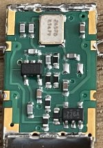
The purple circles highlight the ground point for the signal generation. Here I have a pour hole to prevent capacitive coupling for the oscillator (blindly following recommendations here) however that does mean that the signal return path to the oscillator ground has to find it's way around the hole creating EMI. I would question how much hole is actually needed- the oscillator itself is actually on a double sided board with the back of the oscillator board (on the outside facing the world) is actually a complete copper pour. (see attached images of my previous dead CCHD).
The only thing I can think of is ensuring that there's minimal currents across the ground cage that surrounds. The external signal will have both reflections and noise on the signal return coming through the BNC shield. So this may be better as @1audio has indicated using an isolating pulse transformer to prevent the noisy return from getting to the signal ground reference (purple circle on the buffer chip).

I did look at area A - that area under the THT resistor for the incoming power. I was wondering if a small tongue of V+ as a guard rail would help provide a lower impedance path under the THT resistor for the return current on the opposite side of the board.. BUT.. it's dI/dt and there'd be no change in current only a stable voltage. So I decided to leave that as ground pour. It would have also made a larger island for the noise from right side of the board.
I'm looking at area B and thinking that's hideously complex - it has ferrite chokes in Z form that, from real world testing, that provide some good but mind blowing reduction of noise. The real noise killer is the titchy 600R ferrite bead which really kicks the incoming SMPS noise - so I suspect that is the case for the ~24MHz noise from the OSC and the buffer power rails. I will experiment today with the signal generator and the noise impact on that. If they don't earn their position on the board then they're out. I can also then check the dB attenuation for each.
C17 is looking like a candidate for deletion too. I'd need to look more closely at the schematic.
The purple circles highlight the ground point for the signal generation. Here I have a pour hole to prevent capacitive coupling for the oscillator (blindly following recommendations here) however that does mean that the signal return path to the oscillator ground has to find it's way around the hole creating EMI. I would question how much hole is actually needed- the oscillator itself is actually on a double sided board with the back of the oscillator board (on the outside facing the world) is actually a complete copper pour. (see attached images of my previous dead CCHD).
The only thing I can think of is ensuring that there's minimal currents across the ground cage that surrounds. The external signal will have both reflections and noise on the signal return coming through the BNC shield. So this may be better as @1audio has indicated using an isolating pulse transformer to prevent the noisy return from getting to the signal ground reference (purple circle on the buffer chip).
I did look at area A - that area under the THT resistor for the incoming power. I was wondering if a small tongue of V+ as a guard rail would help provide a lower impedance path under the THT resistor for the return current on the opposite side of the board.. BUT.. it's dI/dt and there'd be no change in current only a stable voltage. So I decided to leave that as ground pour. It would have also made a larger island for the noise from right side of the board.
I'm looking at area B and thinking that's hideously complex - it has ferrite chokes in Z form that, from real world testing, that provide some good but mind blowing reduction of noise. The real noise killer is the titchy 600R ferrite bead which really kicks the incoming SMPS noise - so I suspect that is the case for the ~24MHz noise from the OSC and the buffer power rails. I will experiment today with the signal generator and the noise impact on that. If they don't earn their position on the board then they're out. I can also then check the dB attenuation for each.
C17 is looking like a candidate for deletion too. I'd need to look more closely at the schematic.
Attachments
So 3.3Vpp (+10dBV) square wave sweeping 20-25MHz input. through both a ferrite choke in Z configuration (down to 34mV), then the 600R ferrite down to 10mVpp which is basically the background noise if the probe is not connected. That's a decent ~50 dB reduction.

Last edited:
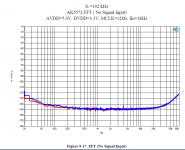
Ok I have my 3080 regulators setup with the ADC just with the regs on protoboard and on the bench unshielded- first reading at 4Mpt .. that's not a bad noise level drop. No ferrites etc just the regulators. The clocking is done via the sig gen just so I have a gauge to previous readings.
I just worked out I had dBFS on, switching to dBV like the previous readings I get:

I just worked out I had dBFS on, switching to dBV like the previous readings I get:
Last edited:
I have started looking at some SMT shielded RF pulse transformers as I'm concerned with the return noise causing ground bounce for the buffer.RE transformer- Its been years since I did that project. The notes are lost in the bit bucket of time. However this transformer would work fine: https://www.mouser.com/datasheet/2/1030/TC1_1TG2_2b-1701376.pdf What I would do is set up a local xtal oscillator and drive it with the transformer (injection lock). Or you could use a suitable fast comparator (e.g. https://www.mouser.com/datasheet/2/609/AD8611_8612-1502365.pdf) tied directly to the transformer with a termination. I do not remember seeing any ringing.
I'm also going to try setting up a small linux VM with some open source tools, convert the PCB and see if it can model the electrical fields on the PCB. There's a GitHub tool that can take the pub file from Kicad and convert it to the tool format.
So power supplies, decoupling all about the inductance of the power rail.. it even targets the myth of 3 different values for switching..
Last edited:
So an ADC update 😀
1. unshielded external Protoboard LT3080 supplies without HF ferrites etc - just between the SMPS and the ADC.
2. Protoboard Digital Isolator with @1audio's original shunt (5V to 3.3V) + isolation IC - this is between the STM and the ADC thus isolating all the i2s.
3. Still using the noisy SDG signal generator for master clock.
4. lid loose closed on top
That's not a bad noise floor drop. I still have some additional thing I want to do (and I want to order the clock PCB this week).
It's just struck me that that's only to 42KHz not the full scale, not sure how I managed that.
I've also explored the grounding - this is just now with the only two grounding points being (a) the BNC to the SDG and (b) the USB shield that may or may not be touching the shell (thin slot for mini usb). First averages from power up look good:

Removing that ground loop has massively reduced the amount of harmonics and spray across the spectrum. I suspect the 100kHz rise being SMPS bench power supply switching noise (rated 120mVpp of ripple). It looks like there's a peak and spurs in that which is why it looks more like a hard signal with a fundamental at 100kHz rather than a rise in a broadband noise floor. I'll look at adding a common mode ferrite choke to the power and possibly a 15mF RC filter to simulate the linear power supply I am looking to put in - I may use a separate box with an umbilical as there's not much space in the box.
Additional to this is that currently the i2s is carried by unshielded ribbon cable which will be radiating all sorts of noise.
Letting the system warm up and stabilise (it's now drawing 110mA and 59mA from each of the two 18V floating supplies). I can see more detail:

Without that obvious ground loop and the extra detail I can now see the 100kHz peak is really nasty. I'll try putting in a CMC however the ones I have available are targeting the 24-25MHz at maximum impedance rather than 100kHz. The LT3080 will have rolled off in their PSRR by that point too.
Another alternative is that the 100kHz noise is coming from the SDG that's currently generating the master clock. With a 1kHz signal, the noise floor is above that spike. I could test that theory by using a high pass filter with the 50R connection of the clock as R and use a 10uH inductor to provide a -20dB attention at 100kHz.
However for now I'm going to focus on the clock PCB which will remove one more ground loop/noise point on the system.
So the the clock - I've started on a new PCB layout using a 4 layer stack and using microstrips for the signal path. I've also switched the THT components to their SMT SOT23 equivalents along with many of the other components to reduce the loop sizes. The power dissipation for the SOT23 packages is 200mW but the LTSpice sim seems to show about 14mW each which would be acceptable. The 4 layer should reduce RMI and the enclosed microstrip should slow the transitions too.
I've also explored the grounding - this is just now with the only two grounding points being (a) the BNC to the SDG and (b) the USB shield that may or may not be touching the shell (thin slot for mini usb). First averages from power up look good:
Removing that ground loop has massively reduced the amount of harmonics and spray across the spectrum. I suspect the 100kHz rise being SMPS bench power supply switching noise (rated 120mVpp of ripple). It looks like there's a peak and spurs in that which is why it looks more like a hard signal with a fundamental at 100kHz rather than a rise in a broadband noise floor. I'll look at adding a common mode ferrite choke to the power and possibly a 15mF RC filter to simulate the linear power supply I am looking to put in - I may use a separate box with an umbilical as there's not much space in the box.
Additional to this is that currently the i2s is carried by unshielded ribbon cable which will be radiating all sorts of noise.
Letting the system warm up and stabilise (it's now drawing 110mA and 59mA from each of the two 18V floating supplies). I can see more detail:
Without that obvious ground loop and the extra detail I can now see the 100kHz peak is really nasty. I'll try putting in a CMC however the ones I have available are targeting the 24-25MHz at maximum impedance rather than 100kHz. The LT3080 will have rolled off in their PSRR by that point too.
Another alternative is that the 100kHz noise is coming from the SDG that's currently generating the master clock. With a 1kHz signal, the noise floor is above that spike. I could test that theory by using a high pass filter with the 50R connection of the clock as R and use a 10uH inductor to provide a -20dB attention at 100kHz.
However for now I'm going to focus on the clock PCB which will remove one more ground loop/noise point on the system.
So the the clock - I've started on a new PCB layout using a 4 layer stack and using microstrips for the signal path. I've also switched the THT components to their SMT SOT23 equivalents along with many of the other components to reduce the loop sizes. The power dissipation for the SOT23 packages is 200mW but the LTSpice sim seems to show about 14mW each which would be acceptable. The 4 layer should reduce RMI and the enclosed microstrip should slow the transitions too.
Last edited:
Hehe putting the 15mF caps across the input for the regulators (between the SMPS and the regulator) has resulted in this lovely display:

That's a considerable reduction in LF noise which is good.
That's a considerable reduction in LF noise which is good.
That rise of the noisefloor towards 100kHz is due to ADC noise shaping. The 100kHz peak is something else.
Agreed - I think there's a 100kHz fundamental which is then comes into the noise shaping and results in further noise. I'm ok with the noise shaping but just want to get the entire noise floor under 140dBV (my target). I'll have to check the power supplies and the SDG and see if I can spot anything on the scope FFT (setup so it's focuses on that region with the sensitivity turned up.)
Using the THD distortion settings with a LPF and HPF, the harmonic filtering means the noise not associated with a harmonic is rejected. The result is 16x average:

Although we're getting closer towards the AKM figures, I would still like to get the clock PCB and PSU finished so that the device is basically standalone with the host.
I think it’s almost quiet enough now for my needs (but still tweekable!).
Although we're getting closer towards the AKM figures, I would still like to get the clock PCB and PSU finished so that the device is basically standalone with the host.
I think it’s almost quiet enough now for my needs (but still tweekable!).
Ok, So I made a 4 layer board which I'll oder from jclpcb. I may add a couple more cap pad. 100mm x 50mm. All vias are through hole to all layers, the signal path for the clock is running on a strip line between two ground layers.

Thinking about this more I think there's a more optimal form - move the mirrored shunt to the right side and shuffle the HF area over to the left. This would mean that there is a short DC loop for the oscillator that doesn't span the SMB connectors and any associated ground current from that.
I could easily cut this down now to a 2 layer too which I may end up doing.
This change could actually be beneficial - I flip the DC shunt on to the back so that it faces up when it's installed, the RF clock side sits on the underside against the metal chassis (making a box) with only the SMB connectors pointing up on the back side of the board.
Red arrows showing the DC loops.
Last edited:
- Home
- Design & Build
- Equipment & Tools
- Nick's audio test system (AK5572 ADC 129KHz 32bit stereo balanced input)