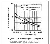
very few RF FET manufacturers provide a graph of noise spectral density. But sometimes there is - I attach a typical exampleI know that BF862 has been used successfully in audio, but their production has been discontinued. Horowitz and Hill name the CPH3910 as a replacement.
Attachments
Thank you, I read the threads where the topic of Aurak was concerned. Even left a post in the technical description thread. It is not clear to me why in the first stage Aurak tried to make a L/R pole shift? It's all confusing. And it's ugly to add a series resistor at the input. You can simply add an extra zero at the frequency of the L/R pole in the second stage, everything will be simple and clear, the cartridge will be tuned with one resistor.Please take your time and explore the linked threads.
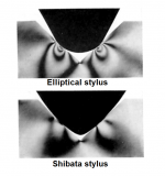
I attach Shibata vs ellipitical, you simply may imagine vs conical/spherical is much worse.Does that mean that your hypothesis is that Shure specifies a rather high recommended load capacitance for their older (high inductance) cartridges because it works well with spherical styli, but that a lower capacitance works better with elliptical styli? Fascinating, as Spock would say.
Attachments
I think the low value resistor in series with the input will add very little noise - it’s swamped by the cart coil resistance - the noise is added RMS style.Thank you, I read the threads where the topic of Aurak was concerned. Even left a post in the technical description thread. It is not clear to me why in the first stage Aurak tried to make a L/R pole shift? It's all confusing. And it's ugly to add a series resistor at the input. You can simply add an extra zero at the frequency of the L/R pole in the second stage, everything will be simple and clear, the cartridge will be tuned with one resistor.
Re JFETs, I would generally accept the information in Horowitz and Hill as sound. They really do a lot of research on these things and the recommendations are spot on. The LSK389 and the new JFE2140 are also excellent parts (I’ve vused both of these and had great results). LSK389 availability has been a problem - weak distribution- they really need to get onto Mouser.
😊
Last edited:
The amount of additional noise depends on the added resistance. But why do it at all? No need to move the cartridge pole to 500 µs, let it stay in its place. It just needs to be compensated. I have my own idea of how to build a transimpedance amplifier. But here it is an offtopic. In what thread is it better to write about it? Or open a new thread?I think the low value resistor in series with the input will add very little noise - it’s swamped by the cart coil resistance - the noise is added RMS style.

As the initiator of this discussion, I think it is quite appropriate to discuss your idea right hereI have my own idea of how to build a transimpedance amplifier. But here it is an offtopic. In what thread is it better to write about it?
Now I'm soldering a prototype to test the idea in practice. It is not clear with the choice of the cutoff frequency of the DC servo. There should be minimal influence in the audio range, but it is highly desirable to suppress the disc warping signal, the level of which at infra-low frequencies can significantly exceed the nominal signal level. The first harmonic of this signal lies at 0.55 Hz, it would be desirable to suppress it by about 20 dB. But this causes a peak of several dB around 20 Hz.
The amount of additional noise depends on the added resistance. But why do it at all? No need to move the cartridge pole to 500 µs, let it stay in its place. It just needs to be compensated. I have my own idea of how to build a transimpedance amplifier. But here it is an offtopic. In what thread is it better to write about it? Or open a new thread?
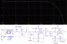
You find the actual components values in the simulation models.
http://waynestegall.com/audio/riaa.htm#mozTocId495677
And here's the 1984 patent he reffers to:
https://patents.google.com/patent/US4470020A/en
Basically ad844 internal guts...Daniel Mohr might have been the actual inventor of ad844...we'll never know for sure unless someone tells us.Wyn Palmer here with us on diyaudio sais he did the AD846...He might know better.
Last edited:
Wayne Stegall explored a few lines himself.The only thing with this is that you need to taylor the feedback for each cart but I suppose there's some wider compatibility with various carts in the +-6db max acceptable riaa variation then we expect.Yes 6db...that's what an independent study found as human ear acceptance for riia response.
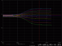
Yes, an adjustment is needed for each cartridge, R5 serves for this. With a classic load of 47k + C, adjustment to the cartridge was also required. Some commercial phono stage had a set of switches for selecting C (rarely also R). Tuning inaccuracy affects the frequency response only near 20 kHz, where nothing is heard. In most cases, the choice of C was made by ear, i.e. randomly and got away with it. For a transimpedance amplifier, an incorrect setting will result in a non-linear frequency response in the middle of the audio range, which will be clearly audible. Therefore, tuning must be done, and this is the main drawback of the transimpedance phono stage. Obviously, this is the reason why such an amplifier did not become popular. A commercial transimpedance phono stage should have a simpler, user-friendly setup. It is possible to apply a scale for the L/R time constant potentiometer and make a table of cartridges. But this method is not very accurate. It is best to measure the frequency response with the cartridge connected. In fact, only two points need to be aligned, eg 100 Hz and 3 kHz. It is also possible to build a test generator and a simple meter inside the phono stage. Or use an external test signal source, for example, a CD with recorded frequencies with RIAA pre-emphasis.The only thing with this is that you need to taylor the feedback for each cart.
Attachments
If you want good RIAA conformity and subsonic filtering, you make the design quite a bit more complicated when you combine a DC bias loop that acts as a subsonic filter with an RIAA amplifier, because the feedback shifts the poles. Any amount of remaining loop gain at 50 Hz will shift the pole that causes the 50 Hz roll-off.Now I'm soldering a prototype to test the idea in practice. It is not clear with the choice of the cutoff frequency of the DC servo. There should be minimal influence in the audio range, but it is highly desirable to suppress the disc warping signal, the level of which at infra-low frequencies can significantly exceed the nominal signal level. The first harmonic of this signal lies at 0.55 Hz, it would be desirable to suppress it by about 20 dB. But this causes a peak of several dB around 20 Hz.
If I were to design something like that, I would calculate the transfer function of the RIAA amplifier with DC bias loop (symbolic calculation, no numbers yet), check if the chosen topology had the desired number of poles, zeros in the origin and a zero elsewhere, and change the topology as often as needed to achieve that. After that, it is probably straightforward to place the negative real zero. For the poles, assuming a second-order high-pass, I would bring the denominator of the transfer function in the form a4s4 + a3s3 + a2s2 + a1s + 1, do the same with the desired pole positions and try to equate the four coefficients of the denominator polynomial to the desired values. You usually don't have to solve any high-order polynomials, only equate the coefficients to the values that you want to have.
Regarding "do the same for the desired pole positions":
When you know that you want to have poles at p1...p4, you just multiply the four factors -s/pi + 1 and then you know what a1...a4 have to be to get the transfer you want.
When you know that you want to have poles at p1...p4, you just multiply the four factors -s/pi + 1 and then you know what a1...a4 have to be to get the transfer you want.
I recently posted a variant of the circuit using a DC servo to form a second-order high-pass filter in this thread.
The main thing here is to set goals correctly. Making a serious rumble and warp filter is a separate problem. Such a filter should combine a high-order high-pass filter (for example, 4th) and a filter that reduces the L-R difference signal below 150 Hz. By the way, I said earlier that I wanted to compensate for crosstalk above 150 Hz. This can be done by slightly modifying the behavior of such a filter. All this requires many nights spent in the simulator, this is the second stage of work. Another possible step is to replace the first op amp, which provides the main gain, with a hybrid amplifier. This will give high loop gain and low noise.
In the first step, I want to make a simple version of the amplifier. The schematic above requires a solution to the issue with the DC offset. An integrator is often used for this purpose, but a very low cutoff frequency is usually chosen. It would be useful to make it not so low as to suppress the warping signal. But the use of an integrator with a high cutoff frequency requires complication, the use of the 2nd order, so as not to get a hump in the frequency response.
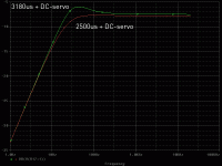
On the other hand, since both stages are inverting, an isolation capacitor is easily connected between them, the DC offset voltage of the second opamp will not be amplified. To get 7950 µs, a capacitance of 1 µF is enough. At a frequency of 0.55 Hz, this results in a -30 dB drop, which is quite good. It turns out a very simple and elegant scheme.
P.S. Sorry for my English, it's not mine at all, but Google Translate 🙂
It will be difficult to calculate the transfer functions of an RIAA amplifier and a servo loop together, many factors will have to be taken into account. For example, it is not entirely clear how to select the DC gain for the servo. It may happen that the op amp of the integrator will saturate faster than the op amp of the amplifier. And in general there is no certainty that it is necessary to use the integrator as a filter for low-frequency signals.
The main thing here is to set goals correctly. Making a serious rumble and warp filter is a separate problem. Such a filter should combine a high-order high-pass filter (for example, 4th) and a filter that reduces the L-R difference signal below 150 Hz. By the way, I said earlier that I wanted to compensate for crosstalk above 150 Hz. This can be done by slightly modifying the behavior of such a filter. All this requires many nights spent in the simulator, this is the second stage of work. Another possible step is to replace the first op amp, which provides the main gain, with a hybrid amplifier. This will give high loop gain and low noise.
In the first step, I want to make a simple version of the amplifier. The schematic above requires a solution to the issue with the DC offset. An integrator is often used for this purpose, but a very low cutoff frequency is usually chosen. It would be useful to make it not so low as to suppress the warping signal. But the use of an integrator with a high cutoff frequency requires complication, the use of the 2nd order, so as not to get a hump in the frequency response.
On the other hand, since both stages are inverting, an isolation capacitor is easily connected between them, the DC offset voltage of the second opamp will not be amplified. To get 7950 µs, a capacitance of 1 µF is enough. At a frequency of 0.55 Hz, this results in a -30 dB drop, which is quite good. It turns out a very simple and elegant scheme.
P.S. Sorry for my English, it's not mine at all, but Google Translate 🙂
It will be difficult to calculate the transfer functions of an RIAA amplifier and a servo loop together, many factors will have to be taken into account. For example, it is not entirely clear how to select the DC gain for the servo. It may happen that the op amp of the integrator will saturate faster than the op amp of the amplifier. And in general there is no certainty that it is necessary to use the integrator as a filter for low-frequency signals.
Last edited:
By changing the time constant of 3180 µs, the frequency response hump caused by the DC servo can be eliminated. But the calculation becomes confusing, it is impossible to change something in the integrator without changing the RIAA correction circuits. Probably, filtering rumble and warping is better done in a separate circuit.Any amount of remaining loop gain at 50 Hz will shift the pole that causes the 50 Hz roll-off.
Attachments
All factors will be immediately and automatically taken into account if we do not calculate, but simulate the scheme, best of all in MicrocapIt will be difficult to calculate the transfer functions of an RIAA amplifier and a servo loop together, many factors will have to be taken into account.
Quite the opposite, if you do the calculation properly you get precisely the poles and zeros you want without any trial and error.
Sadly, not only that we by no means can do without measurements for each specific cartridge in order to compensate for the L\R tau, but also that these tau will not necessarily be the same for the right and left channels (the difference can be of tens %), which will entail a phase shift between the left and right channels, and in the most sensitive voice region of several hundred Hz.Yes, an adjustment is needed for each cartridge, R5 serves for this.
The key word here is properly, but Leoniv rightly complains that "difficult to calculate the transfer functions of an RIAA amplifier and a servo loop together". So why not to simulate outright in Microcap literally in seconds, especially considering its ability to automatically optimize any parameter (for example, flattest freqresp at LF)?Quite the opposite, if you do the calculation properly you get precisely the poles and zeros you want without any trial and error.
Last edited:
- Home
- Vendor's Bazaar
- Nick Sukhov SU-XXI MM Phono stage -85 dBA SN ratio...