my bad
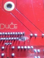
i had my inputs crossed ground to signal vise versa all good now sweet amp. and pins i had soldered are ok pins 1,3 and 5, cleaned them up quick re solder and voila = beautifull music. thank you peranders now i can finish 3 more pcb's two bridged mono's and one more stereo.new chassis almost done.pics
i had my inputs crossed ground to signal vise versa all good now sweet amp. and pins i had soldered are ok pins 1,3 and 5, cleaned them up quick re solder and voila = beautifull music. thank you peranders now i can finish 3 more pcb's two bridged mono's and one more stereo.new chassis almost done.pics
Attachments
pa03 power supply
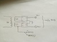
I am building 2 active speakers , as amplifiers ill use 2 of the pa03 boards.
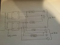
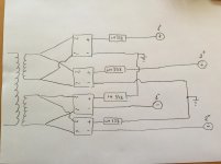
now the question is if i can use external rectifiers, since i have one big transformer and i plan to power both of the boards with it.
its going to look like this in my ugly drawing.
I am building 2 active speakers , as amplifiers ill use 2 of the pa03 boards.
now the question is if i can use external rectifiers, since i have one big transformer and i plan to power both of the boards with it.
its going to look like this in my ugly drawing.
Attachments
the two transformer wired like post162 will work.
But the voltage from 25Vac transformers will be around ±35Vdc
Only suitable with 8ohms speakers, not suitable for 4 to 8ohms, nor for 4ohms speakers.
Are the two AC tappings for an AC detect and trigger to OFF if mains fails?
But the voltage from 25Vac transformers will be around ±35Vdc
Only suitable with 8ohms speakers, not suitable for 4 to 8ohms, nor for 4ohms speakers.
Are the two AC tappings for an AC detect and trigger to OFF if mains fails?
thank you AndrewT.
I am aware of the impedance needed for speakers.
i might end up using these pa03 boards in parallel configuration , because of the transformers.
this is what Parenders said in post #742 in the Pavel Dudek's super Gainclone group buy "If you don't have 50/60 Hz AC in, your delay circuit won't work but it's not that hard to create an oscillator for that".
Potential ground loop problem. Probably better to have only a single ground point and place this close to the amp boards.
Thanks for your answers.
I have a few lm338 boards I ordered from dirtycheap and I'll give it a try , I'll let you guys know if it works .
I have a few lm338 boards I ordered from dirtycheap and I'll give it a try , I'll let you guys know if it works .
If you use +ve regulators then you must use independent PSUs upto the regs.
Dual secondaries to dual rectifiers to dual regs and finally series connect the reg outputs.
Dual secondaries to dual rectifiers to dual regs and finally series connect the reg outputs.
Hi all
Thanks for help last time and sorry for the failed picture uploading.
I've now made two tests and took two some measurements (TP1-2 & TP3-4).
First test is done with the dim bulb test (20W bulb) and the second one is without. Here is the results:
1) With DBT: TP1 & 2 = 23,8 vdc. TP3 & 4 = 0 vdc
2) Without DBT: TP1 & 2 =23,8 vdc. TP3 & 4 = 0 vdc
As you can see the results are exactly the same and that worries me. Why is the output voltage (TP1 & 2) still 23,8 vdc on test 2?
The potential source of error could be me or the multimeter I bought today. When I measured I just put the one tip of the multimeter on TP1 and the second on TP2, correct?
Any inputs or thoughts? Thanks in advance
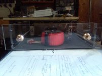
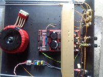
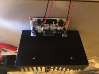
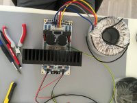
Here are some picture of the build 🙂
Thanks for help last time and sorry for the failed picture uploading.
I've now made two tests and took two some measurements (TP1-2 & TP3-4).
First test is done with the dim bulb test (20W bulb) and the second one is without. Here is the results:
1) With DBT: TP1 & 2 = 23,8 vdc. TP3 & 4 = 0 vdc
2) Without DBT: TP1 & 2 =23,8 vdc. TP3 & 4 = 0 vdc
As you can see the results are exactly the same and that worries me. Why is the output voltage (TP1 & 2) still 23,8 vdc on test 2?
The potential source of error could be me or the multimeter I bought today. When I measured I just put the one tip of the multimeter on TP1 and the second on TP2, correct?
Any inputs or thoughts? Thanks in advance
Here are some picture of the build 🙂
Attachments

Siha, To me your measurements look okay.
In addition measure TP1 and TP2 to ground. Probably you will see +-12V and that's okay.
Measure rails voltage by removing the fuses. One of your probes on the clip holding the fuse and the other to ground. With a 24V transformer you'll see about +-34V.
Your TP3 and 4 results are excellent.
I look forward to see your finished build and share your listening results with us.
Clog, I made new measurements today and the results are what you forecasted.
TP1 to Ground: 11,8 vDC
TP2 to Ground: 12 vDC
FU1 & FU2 to Ground = 34,6 vDC
I'm trying to understand the results because building and understanding is half the fun 🙂
So, I'm guessing the voltages FU1 & FU1 to ground is the supply voltages (Vcc & Vee) and according to LM4780 data sheet 34 vDC will give me almost 60 W at 8 ohm load, correct?
But I'm not quiet sure if I understand TP1&2 and TP3&4. What does the those measurements tell me?
Newb helps newb, funny🙂
Siha, you are right. On the fuses you measure the rails voltages.
According to Pavel Dudek, the designer of this amp, output power is 2x60W in 4 ohm and 2x45W in 8 ohm.
On TP1 and 2 you check the output voltage of the (12V) voltage regulators and they provide juice for the input opamps.
The DC voltage on TP3 and 4 ideally should be close to zero. Several mV no problem. But a high DC offset could even damage your speakers. Did you measure TP3 and 4 to ground ??
Clog, In this case you are a newb with experience, me...totally fresh 🙂
TP3 to ground = TP4 to ground = 15 mvDc, okay I guess?
I couldn't hold it any longer, so two days ago I connected the speakers and my phone as the source to the amplifier and voila! There was music! I really like how natural the music sounds with this amplifier. Not to spacey and not to narrow, not to warm nor to cold, just balanced music.
Next step is to add a tone control as I feel that I need more bass. Also a rotary switch will be added to select between build in Wifi audio receiver, TV and an auxiliary input. The goal is to build an integrated amp.
Hi...Guys
I am preparing to make a PA03.
I(and one of my friends) have got PCBs through the 4th groupbuy.
I've already ordered the components with reference to the BOM.
Spending some time reading this thread, I must admit the experience and opinion provided here would be great help to my build.
Thanks and I hope I will be back with my own build. =)
TP3 to ground = TP4 to ground = 15 mvDc, okay I guess?
15mV Dc is no problem. Congratulations with your amp and good luck with your ambitious project.
@ksjung88 Building the PA03 is not all too complicated. Thoroughly check every step you make. The result is a very well sounding amp.
- Home
- Amplifiers
- Chip Amps
- Newbee build: PA03 amp (LM4780)